 MIDI Connection Systems
MIDI lets you transfer musical information between a sequencer, musical instruments and other devices. You don’t need to understand any technical details to use it, although most computers also need a special MIDI adaptor box, sometimes known as a MIDI interface.
A MIDI sequencer records how you performed on a musical keyboard. Alternatively, you can employ manual editing to create an entirely new song or to modify an existing sequence. And with suitable hardware you can synchronise the results to a video recording by means of timecode.
MIDI Connection SystemsThe diagram below shows a simple MIDI system using a basic adaptor:-

As you can see, the output of the MIDI keyboard is connected to the input of the adaptor whilst instruments, effects devices, or MIDI-controlled audio mixers are connected to its output.
You can create a daisy-chain on the output, connecting up to three devices via their MIDI Thru sockets. This means that if your adaptor has three outputs you can use a total of nine devices.
The following diagram shows a more sophisticated system in which a MIDI Thru box has been added to expand the number of outputs available from the adaptor. In this example a MIDI merger has also been incorporated. This combines MIDI Timecode (MTC) information with the output from the keyboard. It also allows editing of material within a device (usually in the form of sound samples), providing that both the MIDI inputs and outputs of the device are connected to the system.
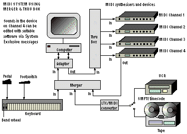
SMPTE timecode can be extracted as an audio signal from a recording track on a video cassette recorder (VCR) or audio tape machine. This form of timecode, known as longitudinal timecode (LTC), is converted into MTC by means of an LTC to MIDI converter.
Finally, here’s an example of a system using an intelligent adaptor:-
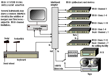
As you can see, this particular adaptor also generates and reads LTC. In addition, the system supports timecode stored as vertical interval timecode (VITC) within the actual video signal of the VCR. This is converted to standard LTC by means of a VITC to LTC converter.
Often one instrument or a dedicated keyboard-only device is employed as a master keyboard. Clearly, you’ll want to hear a sequence as it’s played on the keyboard and recorded into the sequencer. Unfortunately, the keyboard is usually on a different MIDI channel to the instrument. Most sequencers overcome this problem by replacing the channel number of the keyboard by that of the instrument, a process known as auto-channelising or echo. Of course, if you’re using the keyboard as a synthesiser the sequencer must also ‘echo’ data back to the keyboard via its own channel.
Most sequencing applications let you record and echo to any channel, irrespective of the keyboard’s channel. If all synthesisers are in Omni off mode (see below) and are using unique voice channels, you can select and play any sound from the keyboard by selecting an appropriate echo channel.
Local Control off (see below). Any notes you play will then go to its MIDI output but not to its sound generators. However, data arriving at its MIDI input will produce sounds.Standard MIDI messages can be divided in the following groups:-
These include the most common type of message, such as Note On or Note Off. Each instruction of this kind refers to a MIDI channel, identified by a channel number which is normally assigned to a specific voice in each musical device. Any track that’s created in a sequence can be used to play the required voice by sending a message to the appropriate MIDI channel.
Each musical instrument can be set up to respond in one of several modes:-
In Mono mode a single voice is triggered using one MIDI channel and no further sounds can play until this first note has ceased. This unusual and archaic mode is sometimes used to control an elderly analogue synthesiser that’s connected to a modern system via a MIDI to analogue converter.
Poly is a modern mode in which polyphonic sounds of the same voice are triggered using one MIDI channel, whilst non-voice messages are sent via a special channel known as the basic channel. The latter channel can default to channel 1 or can be selected using the instrument’s master controls.
Multiphonic mode, a variation of standard Poly mode. In this state multiple polyphonic sounds can be triggered using a specific MIDI channel for each voice.Omni on mode, which can sometimes be switched on or off in both Poly and Mono modes, allows a single voice to be triggered by all MIDI channels. For polyphonic operation, where more than one note is played at a time, several channels are needed, which means this mode is often best turned off.
Poly and Omni on modes. In other words they should play polyphonically from any channel. In reality, many devices only accept data from selected channels. In Omni off mode a device only accepts data on its basic channel.Program Change message can be used to switch any device on a specified channel into a preset state, but is usually used to select a predetermined sound or voice.Control Change messages are generated from switches, foot pedals, or other controllers that are provided on some MIDI devices. This data can then be used to adjust other devices whilst playing a sequence. Typically, such controls have 14-bit resolution, stretching the capacity of MIDI to the limit. However, the transmitted data can be thinned, usually with little audible effect, or the receiving device can be programmed to do the job itself on receipt of a simple MIDI command.
These messages, also known as Sysex messages, often contain manufacturer’s proprietary codes for controlling or editing data in their products. Although details for System Exclusive codes are usually supplied, you’ll often encounter special software that obviates any need to understand them.
Several different types of message are used for synchronising other devices to a sequencer. Initially, the sequencer should send a Song Select message to indicate which song it’s about to play. A Start message should then be sent to the sequencer to initiate playback of the song.
Once it’s running, the sequencer sends regular Timing Clock messages at a rate of 96 clocks per whole note (semi-breve). By using these clocks to modify a ‘song position pointer’ register, each device knows how far the sequence has progressed. To return to a particular point in the sequence the sequencer must send a Song Position Pointer message to all devices.
In addition to the above messages, it’s also possible to convey timecode, the actual time of day of a recording in hours, minutes, seconds and frames. These messages allow other devices such as video and audio equipment to be synchronised to a sequencer. Two systems are used:-
This is the standard system for synchronisation. A Full MIDI Timecode message, also known as a Full Frame message, is sent when the source of timecode starts, stops or ‘drops out’. This is followed by Quarter Frame messages that are sent during a continuous run of timecode.
Full MIDI Timecode message is a System Exclusive message. This point should be kept in mind when using any device that filters MIDI data.Both of these systems, devised by Mark of the Unicorn, are highly reliable alternatives to MTC that only employ System Exclusive messages. A full set of time information is sent at the start of a ‘run’ of timecode, which is then followed by up or down clock messages as timecode progresses.
 MIDI Channel Numbers
MIDI requires every voice or instrument in a device to be assigned a MIDI channel number. However, most drum machines use only one channel for all of the sounds in the device, which is a useful feature when you’re short of MIDI channels. In this instance, each sound is assigned to a different note: this is possible because percussion sounds aren’t normally played at a particular pitch.
Traditionally, any instrument can be assigned to any number, sometimes causing unsuitable sounds to be heard in a sequence. However, devices designed to the General MIDI (GM) convention use a standardised program numbers for common voices. Such GM instruments, containing 128 standard GM sounds, can play sequences without the user having to worry about assignments.
Further extensions to the GM standard include GS, devised by Roland, and XG, developed by Yamaha. Both overcome the limit of 128 sounds provided by GM by using alternative sounds known as variations, as well as special effects. Note that although GS or XG sequences can be played on ‘standard’ MIDI instruments, none of the special GS or XG content will be reproduced.
Many MIDI devices and sequencers can be synchronised to timecode. Timecode indicates the time of day of the original sound or video recording or its duration in hours, minutes, seconds and picture frames in the form hh:mm:ss:ff. The standard is defined by the SMPTE, although the number of frames per second is set by your television standard, usually NTSC or PAL.
00:00:00:00 can upset some sequencers. If this happens, try a non-zero starting point, such as 10:00:00:00. Fortunately, timecode recorded as time of day (rather than programme duration) usually begins with a non-zero value.Timecode can come in various forms, each suited to a particular purpose. When conveyed over a MIDI circuit it’s usually in the guise of MIDI Timecode (MTC), Direct Time Lock (DTL) or Direct Time Lock enhanced (DTLe), as described above. However, it can also be transported in the form of an analogue audio signal, can be embedded in the data carried over a digital audio link or incorporated within a related video signal. These types of timecode are described below.
This is an analogue audio signal that conveys timecode by means of modified bi-phase encoding. It can be recorded onto an audio track of a conventional tape machine, onto the linear audio tracks of a Sony U-matic or similar video recorder or onto the hi-fi audio tracks of a VHS machine.
Timecode can also be conveyed via a digital audio interface, such as the professional AES/EBU audio interface or the domestic Sony/Philips Digital Interface (S/PDIF). Unlike LTC, timecode can be carried at the same time as an audio signal, although timecode can also be conveyed its own. Some professional Digital Audio Tape (DAT) machines can extract timecode from such a signal, although many machines only employ a standard LTC circuit for timecode connections.
VITC is embedded within a video signal, usually the one containing the related pictures. This means that both timecode and video can be recorded onto a video recorder at the same time.
Sometimes, you’ll encounter a non-MIDI device that can be controlled via MIDI. Such a device can be electrically compatible with MIDI, allowing a connection to be made via a simple adaptor cable. In other instances, a special interface box may be required to provide the connection.
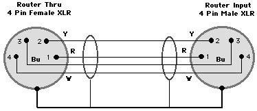
One elderly device, the Akai DP3200, an audio router with 32 inputs and outputs, can be controlled using MIDI instructions, even though it wasn’t originally marketed as a MIDI device. Its control input appears on a 4-pole XLR socket, although this connection is electrically compatible with MIDI. A suitable adaptor cable should be wired as shown below:-

If you want to loop the data onto another router you can use a cable wired as follows:-
The codes required to control this kind of router are given below. Although the data can be modified to make it closer to the MIDI standard it can never be entirely correct. This means that the messages can cause disruption to an intelligent MIDI adaptor or related software.
The standard message is as follows:-
Fn, 01, 82, dd, 83, ss
__________________
n = Router Number (0 to 3)
dd = Destination
00 to 19 =
ss = Source (input) circuit
00 to 19 =
20 = disconnect from
Standard messages for each of the four possible routers on a MIDI circuit are shown below. The messages have been divided up to show the meaning of these codes for a standard MIDI device. Several dummy bytes, shown in blue, have been added to improve MIDI compatibility.
Router 1:
F0, 01, F7 - System
82, dd, 00 - Note Off
83, ss, 00 - Note Off
Router 2:
F1, 01, 00 - MIDI Timecode
82, dd, 00 - Note Off
83, ss, 00 - Note Off
Router 3:
F2, 01, 00 - Song Position
82, dd, 00 - Note Off
83, ss, 00 - Note Off
Router 4:
F3, 01 - Song Select
82, dd, 00 - Note Off
83, ss, 00 - Note Off
All of this data is conveyed as MIDI messages for System Exclusive, MIDI Timecode, Song Position Pointer, Song Select and Note Off, the latter using MIDI channels 3 and 4.
©Ray White 2004.
