A digital audio interface allows equipment such as audio mixers, recording devices or audio processors to be interconnected without degrading the signal quality. Unfortunately, there are different types of interface, most of which are incompatible, although in some instances you can wire a device with an AES/EBU interface to a device fitted with a S/PDIF socket.
Most interfaces convey stereo (2-channel) audio over a single set of wires, although some also require a separate word clock (WC) circuit, which is often wired via a standard BNC connector.
Common interfaces are described in the following sections.
S/PDIF conveys both channels of a stereo signal, usually via an RCA phono (PIN) connector, although some devices use a TOSLink fibre-optic connector. This interface is commonly used for domestic equipment, such as CD/DVD players, Digital Audio Tape (DAT) recorders, and MiniDisc (MD) machines, conveying 16, 20 or 24-bit samples at rates of up to 96 kHz.
S/PDIF in its ‘copper’ form uses a signal level of between 0.5 and 1 volts into a 75 Ω load over an unbalanced circuit. The similarity to a standard television signal makes it suitable for routing through equipment designed for video material. Since it’s meant to operate with 75 Ω cable it can also be used over long distances without equalisation, and in this regard is superior to the professional AES/EBU interface (see below).
Connecting to devices with an AES/EBU interface is possible, although the following points should be noted:-
Further information about connecting different digital interfaces appears elsewhere in this article.
S/PDIF is a domestic version of the AES/EBU interface (see below). The data is assembled in the same way, except for differences in the Channel Status bits (C-bits). It’s possible to interconnect AES/EBU and S/PDIF devices, either directly or via an adaptor box, the latter correcting differences in signal levels or modifying any offending C-bits.
C-bits between the S/PDIF and IEC 958-11 standards (see below).C-bits, such as bit 0 which is different for domestic and professional audio material.The C-bits for S/PDIF are organised as follows:-
| Bit(s) | Function |
|---|---|
| 0 | 0 - Consumer source 1 - Professional source |
| 1 | 0 - Sample contains 1 - Sample contains data • |
| 2 | 0 - Copying prohibited 1 - Copying permitted |
| 3, 4 | 0, 0 - No audio emphasis 1, 0 - 50/15 µs emphasis |
| 5 | 0 - Two-channel audio 1 - Four-channel audio |
| 6, 7 | 0, 0 - Mode 0 Otherwise only bits |
| 8-15 | Category Code of sender 0, 0, 0, 0, 0, 0, 0, 0 1, 0, 0, 0, 0, 0, 0, 0 0, 1, 0, 0, 0, 0, 0, 0 1, 1, 0, 0, 0, 0, 0, 0 1, 1, 0, 0, 0, 0, 0, 1 |
| 16-23 | Reserved (Mode 0 only) |
| 24, 25 | Sampling Rate 0, 0 - 44.1 kHz 0, 1 - 48 kHz 1, 1 - 32 kHz |
• Data samples can include MPEG3, AC3, DTS and other special IEC 61937 formats.
Bits 0 and 1 have the same function in both S/PDIF and AES/EBU data.
Bits 1 to 5 and 24 to 25 (in Mode 0) are copied from the source to destination. This means that the C-bits in recorded material are identical to those contained in the original data.
The most important bits are usually set as follows:-
| Bit | Usual | Notes |
|---|---|---|
| 0 | 0 | Can prevent |
| 1 | 0 | Indicates interface |
| 2 | 1 | Can be ‘0’ to prohibit |
| 3 | 0 | Set to ‘1’ if emphasis |
whilst bits 4-8 are normally at 0. Assuming an SP/DIF input ignores bit 0, bit 2 is 1 (Copy Protect set to off) and bit 3 is 0 (No audio emphasis) then transfer from an AES/EBU source is possible. Bit 2 is usually at 1 in the AES/EBU interface, allowing copying via this kind of connection, even though copying the same material via an S/PDIF circuit may be prohibited.
Apart from the Copy Protect bit (see above), you may not be able to copy material via an S/PDIF when:-
Copy Protect whilst making an original recording prevents any digital copying.SCMS works by recording two bits of data, collectively known as ID6, which are buried within the data recorded onto DAT. These bits control Copy Protection (CP), working as follows:-
| ID6 | Effect |
|---|---|
| 0 | Unlimited copying |
| 10 | No copies (Copy Protect) |
| 11 | One copy, in subsequent |
The system works in conjunction with the S/PDIF Category Codes (see above). The following table shows how this operates in an SCMS-equipped DAT recorder:-
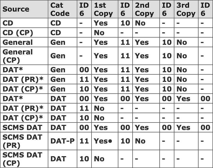
* Pre-SCMS DAT machine: can produce DAT or General Category Codes
(PR) Prerecorded material, including an analogue recording made on an SCMS DAT machine
(CP) Copy-protected material
• During copying, the Category Code is set to DAT-P and the Copy Protect flag is sent via the S/PDIF connection. The receiver always records from a DAT-P source but the Copy Protect flag identifies the material to prevent any further copies.
ID6 is set to 00. This means that even ‘one-copy-allowed’ tapes will be blocked.ID6.This interface, created by the Audio Engineering Society and European Broadcasting Union (AES/EBU) is really a professional version of S/PDIF. It’s connected using a 3-pole XLR connector or, when fitted on a digital audio card, via a standard quarter-inch 3-pole jack.
The signal voltages used by the AES/EBU interface are much higher then those used by S/PDIF and can therefore damage the latter if a direct connection is made. However, the actual data conveyed by the interfaces are so similar that they can sometimes be connected directly or via an adaptor box.
Unfortunately, some equipment responds to the consumer/professional flag within the data stream, refusing any material from the wrong category of equipment. There isn’t any easy way of getting around this problem, apart from buying a specialist device that can modify the flags in the data.
16 or 20-bit samples at 48 or 32 kHz are preferred, although 44.1 kHz can also be used. Unlike S/PDIF, this interface can’t normally be used for 24-bit audio, since the necessary bits are required for other purposes.
The stereo data is carried on a balanced RS-422 circuit with alternating current (AC) coupling, using a signal level of 5 to 10 volts peak-to-peak, working into a 110 Ω load: a transformer is used inside some equipment. The signal can travel over 350 metres of cable without any problems and for even longer wiring you can install equalisation circuits or a repeater device.
As mentioned above, 3-pole XLR connectors are used. The connections are often marked as Digital In (DI) and Digital Out (DO) to avoid confusion with analogue circuits that are also on XLRs.
Further information about connecting different digital interfaces appears elsewhere in this article.
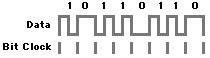
Bi-phase mark encoding is used, eliminating any direct current (DC) component, which means that reversing the wires in the balanced circuit has no effect. This form of encoding also ensures that many of the transitions in the data match the timing of the bit clock, as shown below:-
This arrangement, known as self-clocking, allows the clock signal to be easily extracted at the receiving device. The bit rate is determined by the sampling frequency, as shown below.
| Sampling | Bit |
|---|---|
| 32 | 2.048 |
| 44.1 | 2.8224 |
| 48 | 3.072 |
Data frames are sent out at the same rate as the sampling frequency. Each frame contains two sub-frames, the first containing audio for channel 1 (left), the second for channel 2 (right). The interface also carries non-audio data bits, spread over a number of frames and grouped into blocks. Each block consists of 192 frames, from 0 to 191. Hence the start of frame 0 is called the start of block.
At the beginning of each sub-frame there’s a preamble, which is used by the receiver to extract the sample clock, ensuring that devices at each end of the digital link are synchronised. As shown in the above diagram, there’s normally a transition in the data for each pulse of the bit clock. However, the preamble is made unique by breaking this rule. This coding violation allows the preamble to be easily identified, without confusing it with other data. Different preambles are used to identify each channel and the start of a data block, the latter always being in channel 1. These are illustrated below:-

The sub-frame is made up of the following bits:-
Contains coding violations, as described above.
The four least significant bits are used for 24-bit material or Auxiliary (Aux) data, such as low quality audio, where only 16, 18 or 20-bit coding is used for the main data. The least significant bit (LSB), Bit 0, is sent first. Unused bits are blanked to logical 0 (off).
This is encoded using the standard ‘two’s complement’ method with the LSB sent first.Unused bits are blanked to logical 0 (off).
V-bit)Indicates whether the audio sample is valid. It can also be used to ‘blank’ an unwanted channel on equipment that has separate AES/EBU outputs for channel 1 and channel 2.
U-bit)This can be used in any way. However, a DAT machine with an S/PDIF connection (see below) may use this bit for head drum control, in which case it’s best avoided.
C-bit)This contains special information (see below). The meaning of these flags is different to those used for S/PDIF data.
P-bit)Used to detect an odd number of errors in the sample.
The V, U, C and P bits constitute 4 bits in every sub-frame; in other words, 8 in every frame. Each of these bits appears in every one of the 192 frames contained in each block.
The V and P bits are ‘tied’ to the associated audio sample, whereas the U and C bits, each with a total capacity of 192 bits or 24 bytes, can carry information as required. Note that the data in subsequent blocks needn’t be identical. It may be updated at the interface’s frame rate; around 200 times a second.
Equipment responds to C-bits in various ways. Some devices ignore certain data bits, allowing the audio data to be used, whilst others ‘lock out’ the material if the C-bits aren’t as expected.
The C-bits in the AES/EBU interface operate as follows:-
| Bit(s) | Function |
|---|---|
| 0 | 0 - Consumer material 1 - Professional source |
| 1 | 0 - Sample contains 1 - Sample contains |
| 2, 3, 4 | 0, 0, 0 - Audio Emphasis (Receiving equipment 1, 0, 0 - No audio 1, 1, 0 - 50/15 µs 1, 1, 1 - CCIT J17 |
| 5 | 0 - Sampling frequency 1 - Sampling frequency |
| 6, 7 | 0, 0 - Sampling frequency 0, 1 - 48 kHz 1, 0 - 44.1 kHz 1, 1 - 32 kHz |
| 8- | Channel mode |
| 12- | User bits management |
| 16- | Use of aux sample bits |
| 18- | Source word length & |
| 24- | Multi-channel function |
| 32- | Reserved |
| 48- | Channel origin data |
| 64- | Channel destination data |
| 80- | Local sample |
| 96- | Time of day code |
| 112- | Reliability flags |
| 120- | Cyclic redundancy check |
The usual states for these bits are as follows:-
| Bit | Usual | Notes |
|---|---|---|
| 0 | 1 | Can prevent |
| 1 | 0 | Indicates interface |
| 2 | 1 | Can be ‘0’ if bits 3 |
| 3 | 0 | Set to ‘1’ if emphasis |
| 4 | 0 | Set to ‘1’ only when |
Bits 5-7 are often set to 0 whilst many devices simply ignore bits 8 to 127. When copying between DAT machines the interface doesn’t convey indexing information, also known as start IDs.
In a complex studio system there can be problems with timing between the different digital devices. There are two basic methods of synchronising the equipment in such a system:-
This is similar to the genlock principle used in a television studio. Although perfectly adequate for joining two devices the following puzzles can be encountered in a complex system:-
Note that some devices only become slaves to their input clock when switched into record mode.
This requires a separate clock input on each device, preferably the same as an AES/EBU audio input. Unfortunately many pieces of equipment have a BNC word clock (WC) input instead, which requires a suitable conversion box that accepts a standard AES/EBU master clock.
In a television studio the master clock should be locked to the video frame reference frequency, as well as to the local source of SMPTE timecode. Locking all three of these signals together ensures that sound, vision and timing information are all in step.
Master clocks can have two grades of accuracy, as shown below:-
| Grade | Accuracy in Parts |
|---|---|
| 1 | ±1 |
| 2 | ±10 |
Signals are synchronous if the start of the preamble is within a set margin of the reference clock. Outputs should be within 1⁄20 of the sampling frequency and inputs within ¼. It may be necessary to align the timing of clock inputs by adjustments within the equipment, but once set, it shouldn’t need to be changed again, since drift isn’t usually a problem.
Some sources can’t be locked to the studio system, such as a CD player that provides a nominal output of 44.1 kHz but really operates at 44.098 kHz. Unfortunately, such devices often lack a clock input, whilst others run at the wrong rate, such as a CD player supplying a 44.1 kHz signal to a studio working at 48 kHz. There are three solutions to such problems:-
An alternative type of synchroniser, known as a sample-slip synchroniser, works by dropping or repeating samples during silent periods. Both types of synchroniser perform the special operation once every 20 minutes for a 10 parts per million (ppm) error in sample rate. Another option is a short-term SRC, which uses interpolation to fix the problem at a faster rate.
Most of the following problems can be solved, albeit with expensive hardware:-
C-bits with S/PDIFC-bits giving incorrect flagsSDIF2 is rarely encountered, although it’s commonly employed in early analogue-to-digital converters, as used to adapt a video recorder for digital sound recording.
The interface uses separate 75 Ω BNC connectors for left (L), right (R) and word clock (WC) signals. Each unbalanced circuit uses 5 volt transistor-transistor logic (TTL) levels into a 75 Ω load with direct current (DC) coupling. In a multi-track system several SDIF2 signals, in the form of balanced RS-422 circuits, can be wired via a single 50-way D connector.
SDIF2 conveys audio in 16-bit to 20-bit form, complete with Emphasis and Copy Protect flags. Unfortunately, some equipment ignores these flags, requiring the use of manual switching. Each 32-bit slot, which occupies one cycle of the word clock, is made up as follows:-
| Bit(s) | Function |
|---|---|
| 0-20 | Audio data |
| 21-28 | Control Information |
| 21-25 | 00 - Fixed value |
| 26-27 | 00 - Emphasis ‘off’ 01 - 50/15 µs |
| 28 | 0 - Copying permitted 1 - Copying prohibited |
| 29 | 0 - Not start of block 1 - Start of block User Information |
| 30-32 | Divided into two ‘bits’ of Bit A followed by bit B:- Bit A: 0 - Start of block 1 - Not start of block Bit B: 0 - Not start of block 1 - Start of block |
The most significant bit (MSB) of the audio data is sent first, irrespective of the audio word length. Two’s complement coding is used and unused bits are blanked to 0.
Although a clock is coded into the data itself, it’s ignored by some equipment. This means you’ll have to connect a separate word clock (WC) circuit. If such a clock isn’t provided you’ll hear a cyclic hiss, typically at one or two Hz. The WC circuit carries a square wave signal at the sampling frequency, the rising edge of which is aligned to the start of each data slot.
This interface, also known as Melco, is similar to SDIF2, but doesn’t contain a clock signal in the data. A balanced RS-422 connection is used for each channel and separate word clock (WC) and bit clock (BC) connections are required. It operates with 16-bit or 20-bit audio.
This interface first appeared on Yamaha’s famous DMP7 MIDI-controlled mixer, as well as on its digital successor the DMP7D, allowing several mixers to be ‘cascaded’ together. The connection is made via an 8-pole DIN plug, as shown below:-

This connector conveys two RS-422 signals, one for the audio data and the other for the word clock, wired as follows:-
| Pin(s) | Circuit |
|---|---|
| 1 | Word Clock |
| 2 | Ground |
| 3 | Data |
| 4 | Word Clock |
| 5 | Data |
| 6,7,Case | Screen |
| 8 | Ground/Enable |
Both circuits use direct current (DC) coupling.
A multi-channel interface allows multi-track digital audio equipment to be connected over a single electrical circuit. The most common systems are described below. Unfortunately, some these interfaces are proprietary designs that are incompatible with other systems.
This proprietary interface provides connections to an Alesis Digital Audio Tape (A-DAT) machine, which employs a standard S-VHS video tape to record multi-track digital sound. An optical connector conveys up to eight channels of audio, sampled at 44.1 or 48 kHz. This means that two connectors are needed for an eight-track machine; one for the eight inputs and another for the outputs. In the same way, a 16-track machine requires a total of four A-DAT connectors.
Digital audio cards that accommodate interface usually have a separate 9-pin synchronisation connector, which lets your computer control the transport mechanism of an associated A-DAT machine.
MADI conveys multiple digital audio channels over a single circuit, each channel conforming to the AES/EBU standard. The 56 AES/EBU sub-frames are carried over a 75 Ω coaxial cable, up to 50 metres long, and fitted with BNC connectors. A separate synchronising clock cable is required.
The interface operates at a fixed data rate of 125 Mbit/s, whatever sample rate is used, although the rate at the cable is reduced to 100 Mbit/s by using 4 to 5 bit encoding. This process breaks up each 32 bit sub-frame into 4-bit words, encoded as 5-bit words by means of a look-up table. This form of encoding reduces the direct current (DC) content of the signal.
Synchronisation blocks are inserted at least once per frame. If the link isn’t used to it’s full capacity, extra synchronisation blocks are inserted to ‘fill’ the space on the bus. This is done using a device known as a Transparent Asynchronous Xmitter and Receiver Interface (TAXI).
The AES/EBU sub-frames are as normal, except that the preamble bits 0-3 are replaced by:-
| Bit | Function |
|---|---|
| 0 | Frame Sync flag |
| 1 | Channel On/Off |
| 2 | A/B of stereo pair |
| 3 | Sync block |
This interface is used for connecting Tascam multi-channel digital tape machines. It employs the same optical connector as the A-DAT interface, conveying the same number of channels, although it uses an entirely different data format.
This special interface consists of eight sets of RS-422 mono audio data and a clock signal, all wired via a 25-way D connector. The data itself can be in Yamaha, SDIF2 or Mitsubishi format.
When used in Yamaha format this works in the same way as Yamaha’s stereo interface described above. However, if you feed stereo data into one channel of a multi-channel interface only the left-hand information is received. Also, there’s no direct method available for connecting two channels from a multi-channel device to an input that has a stereo interface.
Most connectors for digital audio are in coaxial form, as used in radio frequency (RF) and video systems. They have a central signal pin, surrounded by a cylinder that provides screening. An appropriate coaxial cable should always be used.
This twist-and-lock coaxial connector is used for SDIF2 and various kinds of video interfaces. It’s also sometimes used for S/PDIF connections in professional systems. The 75 Ω type of connector is most common. Unfortunately, it’s rather too easy to plug this into a similar 50 Ω socket, which often results in jammed or damaged connectors.
This popular connector, also known as an RCA or PIN plug, is used for S/PDIF connections, as well as for video and audio connections in domestic equipment. The older ‘long’ variety of plug can cause problems with sockets that are designed for the modern ‘short’ style of plug.

Recent connectors of this type are gold-plated and highly reliable, although older and cheaper versions are often shoddy. Those that come already moulded-on to a cable are surprisingly good. However, you should ensure that digital audio wiring is always made of real coaxial cable, since conventional audio cables often aren’t suitable for use at high frequencies.
This form of fibre-optic connector, which is often used for S/PDIF circuits, employs a 1 mm plastic fibre-optic cable and visible red light. The high attenuation introduced by this form of fibre limits the maximum cable length to 10 metres or less.
An exceptionally robust connector, also known as a Cannon plug, since this company was one of the first to make this product. The full ‘Cannon’ range of professional connectors come in various types with differing numbers of pins. The 3-pole XLR version can be used for an AES/EBU digital signal or a mono analogue signal over a balanced circuit. Normally the connector is wired in ‘XLR’ order, as shown below. The different terminologies for the wiring are shown for reference:-
| Pin | Circuit |
|---|---|
| 1 | Screen |
| 2 | ▪ Line ▪ Hot ▪ Primary ▪ In phase |
| 3 | ▪ Return ▪ Cold ▪ Secondary ▪ Out of phase |
The shape of a D connector, often used for multi-track audio data, is similar to an elongated ‘D’. It comes in 9, 15, 25 and 35-way form, as well as high density 15 and 50-way versions. The locking screws, often in UNF form, are essential, although metric screws are usually required for attaching connectors to Japanese hardware.
An Amphenol connector is similar to a D connector, but has 14, 28, 36 or 50 plug contacts spread over a central projection. The latches are awkward but are absolutely essential.
Variations in the AES/EBU interface and S/PDIF can make it difficult to connect some devices. The following information is suitable for an electronics hobbyist who wants to create the necessary hardware. Of course, these only work if the actual data is suitable for the receiving device.
The signal level used by the AES/EBU interface is meant to be between 5 and 10 volts peak-to-peak whilst that for S/PDIF is normally in the range of 0.5 to 1 volt. To convert from one to another you can use a simple attenuator, as shown below.

The following circuit is even simpler. However, this variation may upset AES/EBU interfaces that employ electronic balanced circuits in place of a standard transformer.

A transformer can also be added to the output of such an attenuator to ensure that the S/PDIF signal is properly isolated from the ground circuit. This should be in the form of a standard pulse transformer with a winding ratio of 1:1, of the kind commonly fitted in computer network cards.
The less active may consider a ready-made attenuator, usually in the form of an inline device with an XLR socket at one end and a BNC connector at the other. This may also include a transformer.
This is slightly trickier, since you’ll need to increase the signal level. This circuit, derived from articles on Usenet, employs a logic chip containing six inverters, such as the 74HC04 or 4049:-

You may have noticed that this circuit doesn’t have an output transformer, although this can be added to make the whole thing comply exactly with AES/EBU specifications.
As already mentioned, some PC-based hardware provides a digital output via a 2-pin header, also known as an HDR-2 interface. This signal is at Transistor Transistor Logic (TTL) level, giving a signal of 5 volts, which is incompatible with S/PDIF circuits.
The kind of device used for the TTL output may or may not be capable of driving the 75 Ω load presented by an S/PDIF circuit. If it can deliver 12 mA into a 450 Ω load you can employ a simple capacitor-linked attenuator, as shown here:-

Once again, a transformer can be added to the output of this circuit so as to provide ground isolation in strict conformity to the S/PDIF standard (see above).
If your device doesn’t have enough current capacity you can use almost any 5 volt driver chip with an attenuator similar to that shown above, with or without a transformer. This example uses two inverters from a 74HC04 logic chip:-

whilst the circuit below uses the 7HCU04 device from Philips and a custom transformer.

Under some circumstances you may want to convert an S/PDIF signal into a form that can be fed into a standard computer circuit at TTL levels. Here’s a simple solution, again using the 7HCU04 chip:-

whilst the simple circuit shown below includes an adjustment for DC offset, with the voltage on the ‘traveller’ of the preset normally set to around 2.6 volts.

Digital Audio Problem Solvers, Francis Rumsey, Studio Sound, July 1991
Elektor Electronics magazine, Jul/Aug, 1995
Interfacing, Synchronisation and Communication, Francis Rumsey, Digital Information Exchange 1989
Interface and Control for Digital Recorders, Phil Wilton, Broadcast Systems Engineering, January 1987
The Truth about SCMS, Francis Rumsey, Studio Sound, May 1991
©Ray White 2004.
