
To use any type of display, you must have matching video hardware in your computer. Fortunately, most portable and desktop computers have built-in hardware and a monitor socket. Other machines often come with a video card already installed in an available AGP, PCI, NuBus or other type of expansion slot. Your monitor can then be plugged into the video connector on the card.
The connection between a computer and monitor can be digital or analogue. A digital connection may be necessary for an Liquid Crystal Display (LCD) monitor, whilst an analogue interface is required for a Cathode Ray Tube (CRT) display. And, although some LCD devices can work with analogue signals, you’ll always get better results with a digital interface.
Some video interfaces carry extra data between the computer and monitor to control the display. The Display Data Channel (DDC) mechanism is the most common system, often including support for Extended Display Identification Data (EDID).
DDC uses the Inter-Integrated Circuit Bus, more commonly known as the I2C bus, which was originally devised by Philips. This 8-bit bidirectional interface, in which the most significant bit (MSB) is sent first, requires only two wires, a data line and a clock circuit. It runs at 100 kbit/s in standard mode, 400 kbit/s in fast mode and 3.4 Mbit/s in high-speed mode.
If you have an LCD monitor you’ll get best results by using a digital connection, assuming your machine or card provides this kind of output and that the display itself is designed for a digital input.
This kind of connection is really the obvious partner for an LCD screen: the computer simply sends digital instructions to the display, telling it to set the brightness and colour of specific pixels to particular values. This means that the display doesn’t exhibit any of the usual artifacts associated with an analogue connection, such as patterning, jitter or flicker.
The various types of digital connection are described in the following sections.
This proprietary interface, now abandoned, is really a non-standard implementation of DVI (see below). It provides digital signals for an LCD monitor, analogue signals for a CRT display, USB circuits and power. It accommodates almost any type of display, optionally controlled via USB or powered from the supply in the computer. The video data travels over six data pairs, with DDC data sent over separate circuits.
The ADC port appears on a special 35-way socket, as shown below.
This is wired as follows:-
| Pin | Code | Function |
|---|---|---|
| 1 | +25V | +25 |
| 2 | +25V | +25 |
| 3 | LED | Monitor |
| 4 | TX0- | Channel |
| 5 | TX0+ | Channel |
| 6 | SHLD0/5 | Channels |
| 7 | TX5- | Channel |
| 8 | TX5+ | Channel |
| 9 | SDA | DDC |
| 10 | VSYNC | Analogue |
| 11 | SPLY_GND | Display |
| 12 | SPLY_GND | Display |
| 13 | PWRN | Soft |
| 14 | TX1- | Channel |
| 15 | TX1+ | Channel |
| 16 | SHLD1/3 | Channels |
| 17 | TX3- | Channel |
| 18 | TX3+ | Channel |
| 19 | SCL | DDC |
| 20 | SCL_GND | DDC |
| 21 | USB+ | USB |
| 22 | USB- | USB |
| 23 | USB_GND | USB |
| 24 | TX2- | Channel |
| 25 | TX2+ | Channel |
| 26 | SHLD2/4 | Channels |
| 27 | TX4- | Channel |
| 28 | TX4+ | Channel |
| 29 | TXC+ | Clock |
| 30 | TXC- | Clock |
and includes the following analogue connections:-
| Pin | Code | Analogue Function |
|---|---|---|
| C1 | R | Red |
| C2 | G | Green |
| C3 | B | Blue |
| C4 | HSYNC | Horizontal Sync |
| C5 | ANL_GND | Ground |
The interface provides a +25 V feed for powering the display, although any self-powered monitor can also be used. In addition, the PWRN circuit allows the monitor to incorporate a  (Power) button, which is used to start the computer. Similarly, the
 LED circuit can feed an indicator on the display, showing that the machine is actually running.
USB+ and USB- circuits.This digital interface, also known as PanelLink, is for LCD screens. The circuitry, in common with ADC (see above) uses TMDS, this time with four data pairs, plus separate wires for DDC information, the latter also supporting EDID.
The 20-way Mini D Ribbon (MDR-20) socket, as fitted to a computer, is shown below.

This is wired as follows:-
| Pin | Code | Function |
|---|---|---|
| 1 | TX1+ | Channel |
| 2 | TX1- | Channel |
| 3 | SHLD1 | Channel |
| 4 | SHLDC | Clock |
| 5 | TXC+ | Clock |
| 6 | TXC- | Clock |
| 7 | GND | Logic |
| 8 | +5V | +5 |
| 9 | NC | Not |
| 10 | NC | Not |
| 11 | TX2+ | Channel |
| 12 | TX2- | Channel |
| 13 | SHLD2 | Channel |
| 14 | SHLD0 | Channel |
| 15 | TX0+ | Channel |
| 16 | TX0- | Channel |
| 17 | NC | Not |
| 18 | HPD | Hot |
| 19 | SDA | DDC |
| 20 | SCL | DDC |
This type of port, fitted in recent Mac OS machines and PCs, is primarily designed for a DVI display that has a matching DVI socket. It employs Transmission Minimised Differential Signalling (TMDS), with six data pairs for the video material. Separate wires carry the DDC information between the monitor and computer, which can be used to control the monitor.
The DVI port appears on a special 29-way socket, as shown below.

This is wired as follows:-
| Pin | Code | Function |
|---|---|---|
| 1 | TX2- | Channel 2 Data - |
| 2 | TX2+ | Channel 2 Data + |
| 3 | SHLD2/4 | Channels 2 and 4 |
| 4 | TX4- | Channel 4 Data - |
| 5 | TX4+ | Channel 4 Data + |
| 6 | SCL | DDC Clock |
| 7 | SDA | DDC Data |
| 8 | VSYNC | Analogue Vertical |
| 9 | TX1- | Channel 1 Data - |
| 10 | TX1+ | Channel 1 Data + |
| 11 | SHLD1/3 | Channels 1 and 3 |
| 12 | TX3- | Channel 3 Data - |
| 13 | TX3+ | Channel 3 Data + |
| 14 | +5V | +5 V from interface |
| 15 | 5V_GND | Ground for +5 V |
| 16 | HPD | Hot Plug |
| 17 | TX0- | Channel 0 Data - |
| 18 | TX0+ | Channel 0 Data + |
| 19 | SHLD0/5 | Channels 0 and 5 |
| 20 | TX5- | Channel 5 Data - |
| 21 | TX5+ | Channel 5 Data + |
| 22 | SCL_GND | DDC Clock Ground |
| 23 | TXC+ | Clock + |
| 24 | TXC- | Clock - |
• Only used on a DVI-I port, which also conveys analogue signals
* Linked to pin 14 in monitor to indicate monitor is connected, although it may not be powered
Some devices have separate DVI-Digital (DVI-D) and DVI-I ports, the DVI-D port providing standard DVI digital signals, as shown above, whilst the DVI-I variation also supplies SVGA analogue signals, wired to the following additional pins:-
| Pin | Code | Analogue Function |
|---|---|---|
| C1 | R | Red |
| C2 | G | Green |
| C3 | B | Blue |
| C4 | HSYNC | Horizontal Sync |
| C5 | ANL_GND | Ground |
2560 × 1600, requires more data than can be conveyed over a standard DVI circuit, requiring a special video card and a pair of DVI cables.The connections for a CRT monitor are usually analogue, since the display is an analogue device. The circuits are often similar to those in audiovisual equipment, conveying three one-volt signals, representing the intensity of red, green and blue (RGB), as well as synchronisation (synch) signals that keep the monitor’s scanning in step with the computer.
Modern video interfaces, including older non-Apple video cards, generate signals at various refresh rates, resolutions and pixel counts, most of which are accommodated by modern multi-scan or multi-synch monitors. Unfortunately, older types of Apple monitor work at a fixed refresh rate and pixel count, so they’re often unsuitable for use with modern hardware.
Fortunately, most analogue monitors work with almost any suitable video connection, although some older monitors can’t cope with the faster signals produced by newer equipment. Most multi-scan monitors comply to the VGA or SVGA standards, originally designed for used with a PC.
Common analogue interfaces are described in the following sections.
This appears on SGI computers and SGI-compatible video cards. It’s similar to the more common SVGA interface (see below) but appears on the computer as a 13-way plus 3-way D (13W3) socket, as shown below.
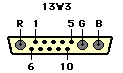
The R, G and B coaxial connections are always used for the Red, Green and Blue circuits respectively, although a greyscale monitor only uses the G connection, this being used for the ‘grey’ signal. The use of the other pins varies, although they always carry signals at TTL levels. A device that supports DDC information is usually connected as follows:-
| Pin | Code | Function |
|---|---|---|
| 1 | SCL | DDC Clock |
| 2 | SDA | DDC Data |
| 3 | CSYNC | Composite Sync |
| 4 | HSYNC | Horizontal Synch |
| 5 | VSYNC | Vertical Sync |
| 6 | +5V | +5 V from |
| 7 | SCL_GND | DDC Ground |
| 8 | GND | Logic Ground |
| 9 | GND | Logic Ground |
| 10 | GND | Logic Ground |
whilst other monitors are normally wired as follows:-
| Pin | Code | Function |
|---|---|---|
| 1 | ID3 | Monitor ID Bit 3 |
| 2 | ID0 | Monitor ID Bit 0 |
| 3 | CSYNC | Composite Sync * |
| 4 | HSYNC | Horizontal Sync • |
| 5 | VSYNC | Vertical Sync • |
| 6 | ID1 | Monitor ID Bit 1 |
| 7 | ID2 | Monitor ID Bit 2 |
| 8 | GND | Logic Ground |
| 9 | GND | Logic Ground |
| 10 | SYNC_GND | Sync Ground |
* Active Low
• Active High
Other computers, including some PowerPC-based machines and Sun workstations, also use the 13W3 connector, again with the R, G and B circuits on the same pins, but with various assignments to the other pins. The PowerPC connections are:-
| Pin | Code | Function |
|---|---|---|
| 1 | ID2 | Monitor ID Bit 2 |
| 2 | ID3 | Monitor ID Bit 3 |
| 3 | TEST | Self Test |
| 4 | GND | Logic Ground |
| 5 | HSYNC | Horizontal Sync |
| 6 | ID0 | Monitor ID Bit 0 |
| 7 | ID1 | Monitor ID Bit 1 |
| 8 | NC | Not connected |
| 9 | VSYNC | Vertical Sync |
| 10 | GND | Logic Ground |
whilst modern Sun workstations are wired as follows:-
| Pin | Code | Function |
|---|---|---|
| 1 | NC | Not connected |
| 2 | NC | Not connected |
| 3 | ID2 | Monitor ID Bit 2 |
| 4 | GND | Logic Ground |
| 5 | CSYNC | Composite Sync |
| 6 | NC | Not connected |
| 7 | NC | Not connected |
| 8 | ID1 | Monitor ID Bit 1 |
| 9 | ID0 | Monitor ID Bit 0 |
| 10 | CS_GND | Composite Sync |
The latter normally supports monitors of 1152 × 900 or 1280 × 1024 pixels, running at vertical scan rates of 66 or 76 Hz.
Many modern computers and video cards are fitted with a standard VGA/SVGA 15-way high-density D (HD15) socket. This connector, which has three rows of pins, shouldn’t be confused with the older 15 way D (DB15) plug that only has two rows, as used on earlier Apple computers and monitors. The modern HD15 socket is illustrated below.

This socket matches the plug fitted to nearly all VGA and SVGA monitors. Hence you can usually connect a monitor using a cable fitted with an HD15 plug and socket.
The connector is commonly wired as follows:-
| Pin | Code | Function |
|---|---|---|
| 1 | R | Red |
| 2 | G | Green |
| 3 | B | Blue |
| 4 | ID2 | Monitor ID 2 ‡ |
| 5 | NC | Not connected ‡ |
| 6 | R_GND | Red Ground |
| 7 | G_GND | Green Ground |
| 8 | B_GND | Blue Ground |
| 9 | - | No pin (key) # |
| 10 | SYNC_GND | Sync Ground |
| 11 | ID0 | Monitor ID 0 * ‡ |
| 12 | ID1 | Monitor ID 1 • |
| 13 | HSYNC | Horizontal Sync |
| 14 | VSYNC | Vertical Sync |
| 15 | NC | Not connected † |
‡ Commonly connected to ground
# Used for +5 V supply from interface in some Apple hardware
* Optional circuit connected to ground to indicate colour in older colour monitors
• Connected to ground in some mono monitors, later used for DDC data (SDA)
† Used for DDC clock (SCL) in later hardware
Note that only the G and G_GND circuits are used in a monochrome monitor. SVGA and XGA hardware normally supports line rates of 31.5 to 117 kHz and frame rates of 40 to 100 Hz, although VGA supports only 31.5 kHz and 60 to 70 Hz.
VGA circuits can also appear on a 9-way D socket (DB9), as shown below:-

which is wired as follows:-
| Pin | Code | Function |
|---|---|---|
| 1 | R | Red |
| 2 | G | Green |
| 3 | B | Blue |
| 4 | HSYNC | Horizontal Sync * |
| 5 | VSYNC | Vertical Sync • |
| 6 | R_GND | Red Ground |
| 7 | G_GND | Green Ground |
| 8 | B_GND | Blue Ground |
| 9 | SYNC_GND | Sync Ground |
* Composite Sync (CS) on IBM PGC
• Not connected on IBM PGC
Older Apple monitors and computers have a 15-way D (DB15) socket, as illustrated below:

which is wired as follows:-
| Pin | Code | Function |
|---|---|---|
| 1 | R_GND | Red Ground |
| 2 | R | Red |
| 3 | CS | Composite Sync |
| 4 | ID0 | Monitor ID 0 |
| 5 | G | Green |
| 6 | G_GND | Green Ground |
| 7 | ID1 | Monitor ID 1 |
| 8 | NC | Not connected |
| 9 | B | Blue |
| 10 | ID2 | Monitor ID 2 |
| 11 | CS/VS_GND | Composite/ |
| 12 | VSYNC | Vertical Sync |
| 13 | B_GND | Blue Ground |
| 14 | HS_GND | Horizontal Sync |
| 15 | HSYNC | Horizontal Sync |
The computer and monitor are normally connected via a plug-to-plug cable. However, some third-party video cards have a D socket with integral coaxial contacts or another connector, requiring an adaptor cable or an inline adaptor.
If your monitor has separate BNC coaxial sockets for red, green and blue circuits, and sometimes for synchronisation as well, you’ll need a suitable adaptor cable. Sometimes only three plugs are used, with composite synchronisation sent over the green circuit. In other cases the synchronisation is sent on its own, sometimes separated into horizontal synchronisation and vertical synchronisation signals, demanding a total of five or six plugs.
To connect a VGA or SVGA monitor to an Apple DB15 port you’ll need an adaptor cable or inline adaptor, fitted with a DB15 plug for the computer or video card and an HD15 socket for the monitor, wired as follows:-
| Signal | DB15 | HD15 |
|---|---|---|
| Red | 2 | 1 |
| Green | 5 | 2 |
| Blue | 9 | 3 |
| Red Ground | 1 | 6 |
| Green Ground | 6 | 7 |
| Blue Ground | 13 | 8 |
| Horizontal Sync | 15 | 13 |
| Vertical Sync | 12 | 14 |
| Horiz Sync Ground | 14 | 10 |
| Composite/Vertical | 11 | 4 |
If you don’t want to make your own adaptor cable you can buy an inline adaptor from your Apple dealer. Just push the adaptor into the back of your computer and then plug in a standard SVGA cable.
 Obsolete Interfaces
Even if you can make them work, most older monitors give inferior results when connected to a modern computer. The original PC and other older computers generate logical video signals that are incompatible with the analogue signals required by a modern monitor. These outdated RGB interfaces employ 5 volt transistor-transistor logic (TTL) signals. In a simple TTL interface only eight shades of colour are produced, since each primary colour is simply on or off.
You can’t use a TTL monitor with a modern machine unless you do one of the following:-
The results will be ghastly compared to a modern display, although old TTL monitors can be obtained very cheaply. In addition, most monitors of this kind are designed for low resolution (LR) video formats. Remember, a TTL monitor simply can’t cope with the signal from a modern video card.
To summarise, all TTL monitors should be consigned to the dust-cart of history.
The original PC accepted a Monochrome Display Adaptor (MDA), Colour Graphics Adaptor (CGA) or Enhanced Graphics Adaptor (EGA) card in an expansion slot. Each adaptor works in two basic modes. In a text mode (T) each character is simply placed on the screen, but in a graphics mode (G) each item is drawn pixel-by-pixel. The standard video modes are:-
| Bits | W | H | Res | Types | ||
|---|---|---|---|---|---|---|
| 0 | T | 1 | 40 | 25 | - | CGA |
| 1 | T | 16 | 40 | 25 | - | CGA |
| 2 | T | 1 | 80 | 25 | - | CGA |
| 3 | T | 16 | 80 | 25 | - | CGA |
| 4 | G | 4 | 320 | 200 | Med | CGA |
| 5 | G | 1 | 320 | 200 | Med | CGA |
| 6 | G | 2 | 640 | 200 | High | CGA |
| 7 | T | 1 | 80 | 25 | - | MDA |
| 8 | G | 16 | 160 | 200 | Low | Special |
| 9 | G | 16 | 320 | 200 | Med | Special |
| 10 | G | 4 | 640 | 200 | High | Special |
| 13 | G | 16 | 320 | 200 | Med | EGA |
| 14 | G | 16 | 640 | 200 | High | EGA |
| 15 | G | 1 | 640 | 200 | High | EGA |
| 16 | G | 64 | 640 | 200 | High | EGA |
Note that 1-bit video can only produce monochrome images or text, with an increasing number of bits accommodating more colours.
Besides these modes, an MDA or Hercules Graphics card can be used for monochrome graphics at 720 by 350 pixels. Other products may produce monochrome or colour graphics at 720 × 348 pixels. Unfortunately, all the above graphics modes use interlaced scanning.
In the MDA and CGA text modes a character box of 8 × 13 dots is used, although each character only occupies a box of 7 × 13, allowing for spaces between characters. CGA can also use 8 × 8 characters, although these look absolutely dreadful.
EGA is a replacement for MDA and CGA. It creates graphics at up to 640 × 350 pixels and in text mode produces reasonable characters of 8 × 14 dots. Super EGA (SEGA) is similar to EGA but provides graphics at up to 640 × 480 pixels.
The MDA, CGA, EGA and SEGA interfaces use a 9-way D socket (DB9), as shown below:-

This connector is wired as follows:-
| Pin | MDA | CGA | EGA/SEGA |
|---|---|---|---|
| 1 | Ground | Ground | Ground |
| 2 | Ground | Ground | Secondary |
| 3 | - | Red | Primary |
| 4 | - | Green | Primary |
| 5 | - | Blue | Primary |
| 6 | Int | Int | Secondary |
| 7 | Mono | - | Secondary |
| 8 | Horiz | Horiz | Horiz |
| 9 | Vert | Vert | Horiz |
The intensity circuit (Int) in CGA creates 16 shades by switching the display’s intensity from to bright to dim. If this circuit is missing the display still works but is limited to eight shades. EGA and SEGA provide 64 shades by using three intensity circuits, also known as secondary colour circuits.
The interfaces described in the main part of this document are specifically designed for connecting a computer to a high-quality monitor, giving pixel-by-pixel resolution. Hence they employ specific technologies that are usually incompatible with the circuitry used for standard video or audiovisual equipment.
In some instances, however, you may want to connect the monitor output of your computer to another device. For example, you could send computer-generated images to a video projector or to several video monitors, so as to present your material to a larger audience, or you could transfer the content to a video cassette recorder (VCR) or similar video recording device.
The standard family of VGA or XGA interfaces (see above) can’t normally be connected directly to video devices. However, a connection may be possible if:-
A composite video signal conveys all of the information about a moving image over a single screened wire, which is usually connected via an RCA phono plug, also known as a PIN plug.
Unfortunately, using composite connections can degrade picture quality. The S-Video interface overcomes this by separating the signal into its components, which are then conveyed via multiway cable and a special 4-pin mini-DIN connector.
Some computers provide useful video outputs. For example, some Apple portables have a 4-pole 3.5 mm jack socket that provides an audio output and composite video connection, some PowerBook models have a combined S-Video and composite output socket at the rear of the machine and others have a DVI output that provides a composite signal via a special adaptor.
If your computer doesn’t have a suitable video output you can use a gadget known as a video presenter. This is wired to the normal VGA/SVGA port on your computer, converting the signal into suitable video formats, usually composite video and S-Video, with a SCART connector option. Unfortunately, the results aren’t always impressive, since the digital signals created by computers are significantly different to those produced by conventional video technology.
ePanorama website at www.epanorama.net
©Ray White 2004.
