
The transfer of data over a communications circuit requires appropriate hardware and software. Once these are working you can use various applications for the following services and operations:-
A wide range of hardware is available for interconnecting computers, most of which is designed for the Internet. As well as the hardware itself, you’ll need to deal with the cost of installation and any associated cables. And for Internet access you’ll need to subscribe to a service provider, although some companies can provide all that you need in a single package.
The choice of hardware is a compromise between cost and speed. The latter, measured in kilobits per second (kbit/s), must be considered in two directions. First, there’s the upstream speed, the rate at which you can send data or upload files to a remote computer. Secondly, there’s the downstream speed, the rate a which you can receive data or download files from another machine. Of the two, the latter is more important, since most people receive more data than they send.
The following table shows the various options available in the United Kingdom, in order of mass popularity. The speeds shown here are typical, although higher rates are possible.
| Connection | Down | Up |
|---|---|---|
| Standard | 56 | 56 |
| ADSL | 512 | 256 |
| SDSL | 512 | 512 |
| Cable | 128/512 | 256 |
| ISDN* | 64/128 | 64/128 |
| Leased line | 64/128 | 64/128 |
| Satellite | 400 | 56 |
| Wireless | 128/512 | 256/512 |
Here’s a quick summary of what’s available:-
This lets you convey digital data over a normal phone circuit, also known as the public switched telephone network (PSTN) or plain old telephone service (POTS). Both the caller and the recipient must have a modem connected to their computers. As with a normal telephone call, the link is operated as a dial-up service, only providing a connection when required.
The modem at the sending end modulates the data into an audio signal which the modem at the receiving end demodulates back into data. Speed is seriously limited, since the phone system is designed for speech signals of restricted bandwidth.
An Asymmetric Digital Subscriber Line requires special wiring from your telephone company, as well as an ADSL terminal adaptor (ADSL TA) or an ADSL modem. ADSL is faster and more reliable than a dial-up circuit. When used with a router, it gives a permanent connection to the Internet, requiring you to use personal firewall software for protection against hackers.
Cable-assisted television (CATV), also known as cable TV, employs coaxial cables to carry TV pictures, but can also provide a permanent connection to the Internet. This requires a CATV splitter box for feeding your TV and a special cable modem.
The Integrated Services Digital Network (ISDN) predates ADSL, but is well-established in professional circles. It uses one or more circuits from your local telephone exchange, normally operated as a dial-up service. However, instead of a modem, you’ll need an ISDN terminal adaptor (ISDN TA), ISDN card or USB-to-ISDN adaptor. Such devices support peer-to-peer communication while some TAs also accommodate multilink operation.
This option, sometimes known as a T1 connection, is similar to ISDN but provides a permanent connection, which means you’ll need firewall software to protect yourself against hackers.
You can use your mobile phone for sending and receiving data, preferably in conjunction with a portable computer. Although GSM and other current systems are very slow, the second generation of phones operate at a similar rate as PSTN, and the third generation (3G) are even faster.
Satellite communication offers rates of 400 kbit/s or higher, although early systems used a telephone modem for sending data ‘upstream’. More recent offerings download at 512 kbit/s and upload at 128 kbit/s, both via satellite, with an option for downloading at 2 MB/s. Most parts of the UK can use a 890 mm satellite dish, although a 980 mm version is needed in Northern Ireland and Scotland.
This technology is still emerging, although it will undoubtedly become popular.
Many computers have a built-in modem or accommodate an internal modem. An internal card is usually fitted into a special modem slot or into a PCI slot in your machine. If you have a portable computer, you may be able to fit a special modem card inside the machine or you can install a PCMCIA card modem.
If your computer doesn’t have a built-in modem, or you can’t fit one internally, you’ll have to use an external modem. Modern modems of this type can be connected to a spare USB port on your computer, although a USB hub is necessary if there aren’t enough USB outlets available. If you have an older machine without USB ports, the modem should be connected to a serial port, such as the Modem port on a ‘classic’ Mac OS machine, which has priority over the Printer port.
A modem is usually fitted with a least one telephone connector, often a 4-way or 6-way modular connector known as an RJ11, both types of which accept a 4-way plug. Irrespective of how many many contacts are fitted, only 2 or 3 wires are normally used for the telephone circuit.
If you live in the USA, you can connect the modem to a spare telephone socket with a standard 4-way cable. However, other countries often use different connectors, so you’ll need a special adaptor cable if one doesn’t come with the modem. In the United Kingdom, for example, you’ll need an adaptor fitted with a UK 6-way modular plug. The rest of the information in this section refers specifically to the UK’s connection system, although much of it also applies to other countries.
The diagram below shows how most people connect their modem:-
This isn’t ideal, since two or more phones are sitting across the line at all times, which can limit the real speed of a 56 kbit/s modem. For example, if no phones are connected, the modem runs at 48 to 50 kbit/s, but with four connected the speed often falls to 33.6 or even 28.8 kbit/s. In addition, all the extra wiring can effect the modem’s performance. Worst of all, if someone picks up one of the phones whilst you’re using the modem the link simply collapses and dies.
Fortunately, some modems are fitted with two sockets, allowing the modem to divert the incoming line away from the remaining phones. This is an essential feature if your modem is also used as an answering machine. Ideally, the modem should be connected directly to the incoming line, as shown below:-

Of course, the details can be varied to taste. Some users, for example, prefer to have at least one phone on the incoming line that can be used to check if the modem is working. If your modem doesn’t have a socket for line diversion you can resort to some form of manual switch, although this invariably ends up in the wrong position at the wrong time.
Most telephones employ 2, 4 or 6-wire connection systems, although only two wires are needed for a basic telephone circuit. In the United Kingdom, one of the two extra wires in a 4-wire system is used as a ringing circuit. This also acts as an anti-tinkle circuit, preventing unwanted ringer noises that can be caused by another instrument on the same circuit being picked up or used for pulse-dialling. In some instances the fourth wire is used for special signalling such as recall.
Most circuits from a telephone exchange are in analogue form. However, company buildings and hotels often have their own private automatic branch exchange (PABX), also known as a PBX. These are often in the form of a digital telephone system, although the outlets appear on standard modular sockets. Worse still, the high current digital PBX signals used on these circuits can be lethal to your modem, although some modems do incorporate protective devices. So be warned:-
In theory, those in the building should know if an outlet is suitable. Either way, if the outlet doesn’t work with a standard telephone, it’s almost certainly digital. If you’re lucky, you’ll find a second outlet, marked Data or Dataport, which is designed for a modem. Alternatively, you can plug your modem into a digital line converter and connect this to the digital socket.
The performance of any analogue telephone line is influenced by the following factors:-
You can check the quality of your line with a standard communications application. You’ll also need the phone number of your Internet service provider (ISP). Once the communications application is running, type the following:-
AT&F1¬
ATDT####¬
where ¬ shows where you should press the Return key and #### represents your ISP’s phone number. You should ignore any request for a log-in name. Just type +++ without pressing Return and an OK should appear. Now type the following:-
This should present you with a list of statistics, including Line Quality followed by a number. If this is less than 25 your line should be suitable for operation at 56 kbit/s.
Recent technology has improved the digital performance of conventional telephone circuits. One example is Asymmetric Digital Subscriber Line (ADSL), a system that uses special electronics at the exchange to provide an astonishing data rate.
In theory, ADSL offers a rate of 9,216 kbit/s, or around 1.1 MB/s, for data received downstream and 640 kbit/s for what you send upstream. In practice, it usually runs at 384 kbit/s to 2.5 MB/s downstream and 128 to 256 kbit/s upstream.
The specified data rate is usually ‘shared’ with up to 50 other users, a situation known as a 50:1 contention ratio. Although not a problem at the moment, this could reduce your final speed to 10 kbit/s if ADSL became an over-popular method of connection. Fortunately, business users can use rates of 1,024 or 2,048 kbit/s with a superior 20:1 contention ratio.
50:1 contention ratio, each circuit can accommodate at least 3,400 users. In practice, it’s unlikely that so many would be connected via a single link.Because the data travels so fast, a maximum cable length is imposed between each ADSL subscriber and the local telephone exchange. In the early days this was 2.5 kilometres (km), although this has now increased to 3.5 km. A new technology known as Rate-Adaptive ADSL (RADSL) is also available, extending the distance to 5.5 km, although not all providers support this system. In the United Kingdom, BT has announced that it can now support distances of over 6 km.
ADSL data is usually conveyed via an existing phone line, although the line must be activated for this purpose by your telephone provider. The connection can be provided on an ADSL faceplate, which replaces the original faceplate on your ‘master’ telephone socket. Unfortunately, most providers charge for this kind of alteration, so it’s usually cheaper to employ the self-install method, involving the use of plug-in micro-filters and telephone splitters.
Self-installation is very easy: you insert a micro-filter into your main phone socket and then plug your non-ADSL devices, such as telephones and television set-top boxes into the standard telephone socket on the filter, using standard telephone splitters as necessary. Finally, plug your ADSL equipment into the RJ11 ADSL socket on the front of filter.
Your computer can be connected to the incoming line using one of the following methods:-
An ADSL modem card, when fitted into a spare PCI slot in your computer, offers a marginally higher speed than an Ethernet connection (see below), is easily plugged to your phone line via a standard RJ11 cable and gives an ‘always on’ connection.
ADSL via Ethernet is slightly faster than USB (see below). For a single user, you’ll need an Ethernet ADSL modem, which often gives you ‘dial-up’ access via Point-to-Point Protocol over Ethernet (PPPoE). However, more recent products operate similarly to an ADSL router (see below), giving you an ‘always on’ connection. These devices also use a fixed numerical IP address, which avoids the need for Network Address Translation (NAT), a particular advantage if you’re using the computer as a Web server.
If you have your own local network, an Ethernet connection gives all the computers on the network access to a common ADSL circuit. And if a hardware router is used you don’t even need to install any extra driver software on the computers.
In any event, the RJ11 cable from your incoming line plugs into the Ethernet ADSL modem or ADSL router, which in turn connects to your computer or existing network hardware via standard Ethernet wiring. Note that a crossover Ethernet cable may be required if you only have one computer or where an Ethernet ADSL modem is connected to a separate Ethernet router or Ethernet hub. Here’s a fairly complex arrangement for a networked connection, involving three separate devices:-

although a combined hub and router, as shown below, is more convenient:-
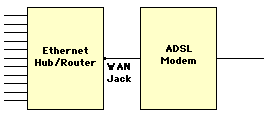
In this case, the ADSL modem is connected via a standard Ethernet cable to the wide area network (WAN) jack or uplink port on the hub. However, if you want to connect the modem directly to a standard Ethernet port on the hub (the same as other computers), you must use a crossover cable.
Finally, the simplest option is an ADSL router, which has the added benefit of providing an ‘always on’ connection:-

Most routers use Network Address Translation (NAT) to protect your computers from the Internet. With NAT, the IP for your local area network (LAN) is in one of the following groups:-
Class A: 10.x.x.x
Class B: 172.x.x.x
Class C: 192.168.x.x
These are private addresses, of which Class C is the most common, although 10.0.0.2, 10.0.0.138, 192.168.0.1, 192.168.1.1 and 192.168.7.1 are used by several types of router.
To use a router in the Mac OS, choose Using DCHP Server in Network Preferences or in the TCP/IP panel. Then plug in the router, open your Web browser and enter http://xx.xx.xx.xx, where xx.xx.xx.xx is the router’s IP address. Finally, fill in the configuration screens: for a BT connection in the United Kingdom you’ll normally enter 0 (zero) for VPI and 38 for VCI.
The computers on your LAN can be automatically configured by selecting Using DHCP Server or entering a unique IP address and a subnet mask. You should also enter the firewall or router LAN IP address in the Router Address field.
Although slightly slower than the above, this low-cost form of connection is ideal for single-computer users, even though it may be a ‘dial-up’ service. The phone line is plugged via an RJ11 cable to an USB ADSL modem, which is connected with a USB cable to a spare USB port on your computer. Note that USB ADSL modems normally require driver software.
The Integrated Services Digital Network (ISDN) uses telephone cables wired directly to you from a local switching centre. These cables are dedicated to data transmission and provide a rate of 64 or 128 kbit/s. Although not much faster than a 56 kbit/s modem, ISDN always runs at these speeds and doesn’t suffer from a system that’s designed for speech signals.
Each ISDN cable conveys up to two Bearer channels (B-channels) running at 64 kbit/s, (56 kbit/s in the USA), which can be combined into a single channel at 128 kbit/s. Protocols for B-channels include PPP, X.25, X.75 (ISDN LAP-B), X.100, T70, BTX, HDLC Transparent, V.110, V.120, channel bundling and bit-rate adaption. Each cable also has a Data channel (D-channel) running at 16 bit/s, which is used for data control purposes and is inaccessible to the user.
For higher data rates you can use more cables, giving correspondingly more channels. The technique of using several channels to effectively create one faster circuit is known as channel bundling. For example, if you have four lines there are 8 channels, giving a total rate of 8 times 64 kbit/s or 256 kbit/s. This allows around 1 MB of data to be transferred in one minute. Up to 30 channels can be bundled, giving a maximum speed over the bearer channels of 1,920 kbit/s.
A coaxial cable or fibre-optic version of ISDN is available, running at 2.048 Mbit/s and giving up to 30 B-channels, plus the extra D-channels. Other variants of ISDN include 1TR6, ESS1, NJ-1, AT&T, TS.013, INSNet64 and Swissnet-2.
In the UK the basic form of ISDN, consisting of a single twisted-pair cable, is known as primary rate ISDN or ISDN2e, where the number ‘2’ indicates the number of B-channels and ‘e’ represents Euro ISDN. When used for phone or fax operation one or both of the B-channels are used as a voice channel. As an option, you can expand primary ISDN to 8, 16 or 30 channels.
A primary ISDN connection box usually has four sockets for using two devices at once, such as:-
The ISDN data circuit on the connection box usually appears as two RJ45 sockets wired in parallel. These can accept one ISDN terminal adaptor (ISDN TA), preferably with the ability to work in multilink mode, or two individual TAs. In most instances, each TA can be connected to a computer via a suitable modem cable or USB cable. Alternatively, if you have a network, you can avoid using terminal adaptors, instead wiring the connection box directly to an ISDN-capable router.
000 as the international dialling prefix instead of 00.To use a single channel of data you only need standard PPP software, as built into the Mac OS. But to use both channels at once requires Multilink PPP (ML-PPP) software, which must also be installed at the other end of the ISDN link.
Unfortunately ML-PP normally ties up both of your channels, preventing you from receiving any normal voice calls. To get around this problem you can employ dynamic bandwidth allocation, a mechanism that works alongside ML-PPP. This lets a single incoming call ‘borrow’ one channel without upsetting the transfer of data, apart from slowing it down. When the voice call is complete the channel is returned to its original use and the data transfer returns to its original speed.
Another option is bandwidth on demand, which normally gives you one data channel. However, when the ‘traffic’ on this channel exceeds a specified level, the link also takes over the second channel until the demand falls.
The two phone numbers given to the ISDN line are usually ‘mapped’ to the sockets fitted on the ISDN box but can be reassigned to the PSTN sockets on the back of a TA by using multiple subscriber numbering (MSN), a mechanism that also lets you use your ISDN connection to run a small telephone system, commonly known as a private branch exchange (PBX).
A mobile telephone, also known as a cellular telephone, is a common accessory for people on the move. When linked to a computer, it can also be used for transferring data. Although several different systems are already in use, other radio-based data transfer systems, such as the Local Multipoint Distribution Service (LMDS) are also being developed.
#06# before the phone is stolen.The standard cellular systems are known as GSM, GPRS, UMTS and HSCSD.
The Global System for Mobile Communications (GSM) is widely used. For example, the GSM 1800 standard, using a frequency of 1800 MHz, operates in over 23 countries, GSM 900 is used in 49 countries and GSM 1900 is employed in the USA and elsewhere. Unfortunately, all forms of GSM are limited to a maximum data rate of 9600 bit/s.
Some GSM phones have an infrared link that can communicate with the matching port on some types of portable computer. Fortunately, IrDA protocol is normally employed, ensuring compatibility with almost any suitable device. Alternatively, you can use a wired connection via a PC card slot or via a USB cable adaptor, together with the appropriate software.
The speed of GSM is totally inadequate. Fortunately, the later second generation (2G) cellular technology, more accurately known as the General Packet Radio Service (GPRS), provides a permanent connection at 56 or 110 kbit/s. Fortunately, GPRS phones also work with GSM signals, although the service is limited to the abilities of the actual network in use.
The third generation (3G) standard, also known as the Universal Mobile Telecommunications System (UMTS), gives higher rates of up to 2 Mbit/s. UMTS phones can also connect to GPRS and GSM networks, although the service may be limited.
There are several other wireless networks not discussed here, including CDPD, CDMA, PDC and Mobitex, as well as the High Speed Circuit Switched Data (HSCSD) system, which gives a transfer rate of 28.6 kbit/s.
If you have an older Mac OS machine without USB, an external modem must be connected to a serial port, usually the Modem port, since this is often given a higher priority. Suitable modems come with a RS-232 interface, often provided via a 25-way D socket (DB25) and with connections configured for data circuit-terminating equipment, also known as data communication equipment (DCE). You may need to construct or obtain an adaptor cable wired as follows:-
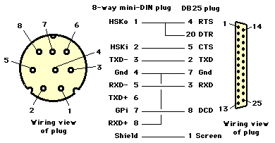
The cable shown above includes wiring for hardware handshaking, which is essential for running a modem at 9.6 kbit/s or higher. Any cable that links pin 2 of the mini-DIN connector to pin 6 on the DB25 connector (DSR), instead of pin 5, is unsuitable for high-speed operation. If you use an even simpler cable that lacks any of these hardware handshake connections your equipment will resort to XON/XOFF software handshaking, which simply isn’t adequate for the job.
Those of a technical disposition may be interested in the following descriptions:-
CTS handshaking must always be used. The RTS and DTR circuits can’t be employed at the same time, although both can be wired, as shown above. The modem is usually configured via an initialisation string (see below) to use either RTS or DTR.
For high-speed operation, the RTS handshaking circuit is best avoided, whilst the DTR circuit can be released for a function determined by the initialisation string. Without RTS handshaking, the computer must always accept data and its serial port must run at a rate equal to or higher than the modem’s maximum speed. If the DTR handshaking circuit isn’t used, its function must be replaced by messages generated by the computer’s software and sent over the TXD- data circuit.
A fast modem isn’t just convenient, it reduces your phone bill. The speed or bit rate for sending data is measured in kilobits per second (kbps or kbit/s), also erroneously known as kilobaud (kbaud). Common values include 1.2, 2.4, 9.6, 14.4, 28.8, 33.6 and 56 kbit/s. To use the Internet you’ll need a modem that runs at 28.8 kbit/s or more, preferably at 56 kbit/s.
The bit rate shouldn’t be confused with the data rate measured in kilobytes per second (KB/s), which is around a tenth of the speed in kbit/s, allowing for the start and stop bits at the beginning and end of each byte. In practice, some bytes are retransmitted if errors are encountered, reducing the actual rate even further. Here are the best possible data rates:-
| Speed | Rate | Rate |
|---|---|---|
| 33.6 | 3.36 | 201.6 |
| 56 | 5.6 | 336 |
If your modem is connected via a serial port then the maximum data transfer rate (DTR) of the port can restrict the speed of your modem. For example, an elderly 680x0-based Mac OS computer with AppleTalk may be limited to 9.6 kbit/s, although this increases to 57.6 kbit/s with AppleTalk turned off. A more recent machine with a GeoPort interface gives 115.2 kbit/s with AppleTalk and 230.4 kbit/s without it. Some of these maximum DTRs can be a problem, especially if your modem is using compression, which increases the speed at the serial port to four times the speed on the phone line.
You can determine the average DTR of your system by using the following equation:-
Ideally, both modems on a link should run at their highest possible speed. In practice, split rates are often used. For example, a V.90 modem (see below), although capable of receiving data at 56 kbit/s, only sends it at 33.6 kbit/s. Fortunately, this usually isn’t a problem, since most people receive more data then they send.
You should always use your modem at the highest possible speed. However, when connecting with another modem the two devices automatically agree over the choice of speed, together with other options for compression and error-control. So if one modem works at 33.6 kbit/s and the other is limited to 28.8 kbit/s the communications session runs at 28.8 kbit/s.
A poor circuit can cause the modems to agree on a very slow rate. When this happens you could try making another call to see if things improve. Just to confuse you, the FCC in the USA have limited the maximum speed of a 56 kbit/s modem to 53 kbit/s. In practice, the actual rate of a 56 kbit/s modem varies somewhere between 46 and 50 kbit/s.
The final speed of a link will match one of the following values in bits/s, irrespective of your modem’s maximum speed:-
| 2400 | 4800 | 7200 | 9600 |
| 12000 | 14400 | 16800 | 19200 |
| 21600 | 24000 | 26400 | 28800 |
| 29333 | 30667 | 31200 | 32000 |
| 33333 | 33600 | 34000 | 34667 |
| 36000 | 37333 | 38000 | 38667 |
| 40000 | 41333 | 42000 | 42667 |
| 44000 | 45333 | 46000 | 46667 |
| 48000 | 49333 | 50000 | 50667 |
| 52000 | 53333 | 54000 | 54667 |
| 56000 |
CR (carriage return) or press Ctrl-C for an ETX (End of Text) message. However, most modern applications don’t require such primitive methods.The International Telegraph and Telephone Committee (CCIT), now known as the International Telecommunications Union (ITU-T) has defined numerous standards for the transmission of data over telephone lines. Fortunately modern modems can be used with most, if not all, of the following standards:-
| CCIT | kbit/s | Notes |
|---|---|---|
| V.21 | 0.3 | Incompatible with |
| V.22 | 1.2 | Incompatible with |
| V.22bis | 2.4 | |
| V.26ter | 2.4 | For noisy |
| V.29 | 9.6 | Group III fax |
| V.32 | 4.8, | Full-duplex |
| V.32bis | 7.2, | Full-duplex |
| V.17 | 14.4 | Group III fax |
| V.34 | 28.8 | |
| V.34bis | 33.6 | |
| V.42bis | 38.4 | |
| V.90 | 56 | Replaces x2 and |
bis = second version of specification
ter = third version of specification
Prior to acceptance of the V.90 standard by the ITU-T there were two competing systems at 56 kbit/s; x2 technology from US Robotics and k56flex from Rockwell. Fortunately, most (but not all) modems can be updated using a flash upgrade. This usually involves downloading data from the Internet, which is then loaded into the modem.
To continue using x2 or k56flex you must use an Internet service provider (ISP) that recognises these standards. It’s worth noting that an ISP sometimes issue special phone numbers for each kind of modem. Although some ISPs accommodate both x2 and k56flex customers, x2 providers are less common. Remember, if you use a modem with the wrong ISP or phone number it won’t work at 56 kbit/s. Ideally, you should get your modem upgraded to V.90.
To avoid file corruption, every block or packet of data must be sent correctly over the link. Following the initial connection, both modems agree on the type of error detection, if any, to be used. Several different techniques have been developed, mainly based on the LAP-B and LAP-M systems. The modern V.42 standard incorporates basic LAP-M error correction, as well as Microcom Networking Protocol (MNP) correction at levels 2 to 4, commonly known as MNP2 to MNP4. The correction mechanism is in the modem’s hardware or in the form of software. Although older modems and software may not fully support V.42, this standard can be used with all ITU-T standards, including the older V.22, V.22bis, V.26ter, V.32 and V.32bis systems. Alternative error correction, such as MNP10, is used for unreliable links via a cellular telephone.
When using these protocols you must set the modem to 8 data bits, no parity and one stop bit. A modem with MNP hardware should confirm that it exists whenever a /REL string is sent to it (see below for more about the Hayes protocol for modems).
Other error correction protocols, including Claris Kermit Tool, XMODEM, YMODEM and ZMODEM, give varying levels of performance. Some of these are supplied as communications tools in the Classic Mac OS and can be selected from within any communications application that supports Apple’s Communications Toolbox (CTB).
Data compression speeds up data transmission, allowing the speed between the modem and a computer to be increased to as much as four times the modem speed. For example, a modem operating at 14.4 kbit/s can use a serial link at 57.6 kbit/s whilst one running at 28.8 kbit/s can use 115.2 kbit/s.
Microcom Networking Protocol Level 5 (MNP5) compression is invariably built into any modem that provides MNP error correction (see above). All recent types of modem provide V.42bis compression, based on the Lempel-Zip-Welch (LZW) technique, giving a compression ratio as high as 4:1. Although V.42bis is up to 40% more efficient than MNP5, modems designed for V.42bis can also use MNP5 if required. However such modern devices often don’t accommodate older communication standards such as V.32 or V.32bis (9.6 and 14.4 kbit/s).
A modem can be used in several different modes, depending on the application and the nature of the link. Each CCIT standard employs one of the following modes:-
If you simply use your modem for working over the Internet you’ll probably never change its basic settings. However, if you want to transfer data directly to another computer by means of a communications application, you may need to set the three basic parameters shown below. The most common settings, which work in most circumstances, are shown in italics.
A fax-modem is a special device that works with your computer to provide similar features to a Group III fax machine. Although faxes are normally sent at 9.6 kbit/s the speed is automatically reduced to 7.2, 4.8 or 2.4 kbit/s whenever the other device can’t cope or when there’s a poor circuit. A real Group III machine can’t work at over 9.6 kbit/s, although 14.4 kbit/s or even 33.6 kbit/s can be used for a fax-modem, assuming the device at the other end can also accommodate such a speed. Some fax-modem software may use JBIG compression to handle graphics that contain shaded material.
A Telecommunications Device for the Deaf (TDD) allows anyone with hearing disabilities to communicate via a keyboard. It operates at speeds used for a Teletype (TTY) or Telex machines, corresponding to 45.5 bit/s in the USA and 50, 110 or 300 bit/s in other countries. Older devices employ Baudot code, although newer models can convey normal ASCII text.
An intelligent modem or terminal adaptor can be controlled using special commands sent from the computer. Most devices recognise a standard set of commands known as the Hayes protocol, although this comes in numerous variations.
Most of the time your computer software and modem uses these codes without you knowing about it. However, in a communications application you can send commands to your modem manually. Each command string sent by the computer begins with AT so as to bring the modem to attention.
Here’s an example instruction that tells the modem to dial a number:-
These instructions are explained as follows:-
| AT | Attention |
| D | Dial a number… |
| T | … using tone dialling |
| *70 | Dials *, 7 and 0 |
| , | Pauses for two seconds |
| 777-2424 | Dials number 777-2424 |
in which the letter T could be replaced by a P for pulse dialling.
Here’s another example:-
which breaks up into:-
| AT | Attention |
| D | Dial a number… |
| T | … using tone dialling |
| 9 | Dials 9 for outside line |
| , | Pauses for two seconds |
| 1(323)4… | Dials number |
Some telephone systems employ call waiting, a mechanism that alerts you to another incoming call by generating a bleep in the background. This is a potential nuisance if it happens whilst you’re using a modem. Depending on your country of origin, you can disable call waiting by using one of the following dialling sequences:-
ATDT*70nnnnn
ATDT*70,,nnnnn
ATDP1170nnnnn
ATDP1170,,nnnnn
where nnnnn represents the number you’re dialling. The commas can be added if your phone system needs pauses in the dialling sequence. The letter W should be added at the end of a sequence if you need to persuade your modem to wait for dialling tone before actually dialling the number.
The following information applies to the United Kingdom:-
ATDT#43#nnnnn, where nnnnn is the phone number, disables call waiting. You can enable it again by dialling *43#. To find out if it’s enabled you can dial *#43#.*40*nnnnn#, where nnnnn is the phone number, makes a call as normal. However, the exchange rings you back afterwards, giving information about the time taken and the cost.1470,nnnnn#, where nnnnn is the phone number, ensures caller ID information is sent. This is necessary if your number is normally withheld but you use an ISP that provides a free service financed from call charges. Such ISPs usually have a number starting with 0845.1471 contacts whoever last rang you. Dialling 1571 gives you access to BT Answer, a free ‘answering machine’ service that stores up to ten messages for up to twenty days.A command string that sets up a modem for particular software is an initialisation string, whilst a string that temporarily modifies the settings for a particular call is a pre-dial initialisation string or pre-dial init. Finally, a deinitialiastion string is used by an application to restore those settings in a modem that existed before it received an initialisation string.
Every Hayes protocol instruction consists of AT followed by a succession of letters and numbers, all of which should be understood by the modem. For example, sending the following message:
and then pressing the Return key, instructs the modem to answer an incoming phone call.
There are many different commands, often varying with the type of modem. The following common commands must be preceded by AT and followed by Return to make them work:-
| Code | Command |
|---|---|
| A | Answer incoming call |
| C0 | Disable data |
| C1 | Enable data |
| DPnnnnn | Dial number nnnnn |
| DTnnnnn | Dial number nnnnn |
| E0 | Echo off (default) |
| E1 | Echo on |
| H | Hang up on caller |
| L0 | Modem speaker |
| L1 | Modem speaker |
| L2 | Modem speaker |
| L3 | Modem speaker |
| M0 | Modem speaker |
| M1 | Modem speaker |
| M2 | Modem speaker |
| O | Switch from command |
| Q0 | Enable user's |
| S0 = n | Answer after |
| S6 = n | Wait n seconds |
| S7 = n | Wait n seconds |
| S8 = n | Pause n seconds |
| S11 = n | Pause n milliseconds |
| V1 | Verbose messages |
| W | Wait for dialling |
| X3 | Dial without |
| X4 | Dial after |
| Z | Reset modem to |
| &A3 | Enable result |
| &B1 | Look serial port |
| &C1 | Use serial port |
| &D0 | Ignore serial port |
| &D1 | Use serial port |
| &D2 | Use serial port |
| &D3 | Use serial port |
| &F | Reset modem to |
| &H1 | Enable serial |
| &R2 | Use serial port |
| &W | Save current |
As you can see, the commands come in two broad groups. Firstly, there are those that contain a letter, such as M0 or H, often followed by a number. Within this group there are special commands that start with S followed by = and another number. Typically, the value of the number n ranges from 0 to 27, although higher values are often used. Secondly, there are commands that begin with an &, followed by a letter, again often followed by a number.
A typical initialisation string contains a combination of the above letters and numbers in any order, although some modems may use numbers that aren’t mentioned above. Here’s a typical string:-
This makes slightly more sense when divided up as follows:-
Here are some other strings for you to consider:-
ATE1V1C0
AT&FE0&B1&H1&R1X4&A3S0
AT&FE0W1Q0V1X4&C1&K3S95
Your modem should also accept a pre-dial init that temporarily sets it up for a particular service. This kind of string ends with a & and can look something like this:-
In this example the code X3 tells the modem to disregard dialling tone. This is necessary in countries such as Italy where the phone system doesn’t always provide such a tone.
Some modems accept commands for special services, such as this ‘Page me’ init string:-
Finally, if you really want to know the current settings of your modem you can enter:-
A really horrible list of information then appears in the window of your communications application.
When working online you can send AT commands to the modem by switching it into command mode. Just type +++, enter your commands and then return to online mode or normal mode by entering ATO. Similarly, if you want to make the modem hang up you can type +++ followed by ATH.
In addition, some types of modem accept really strange commands, such as:-
which turns off modem compression.
Those of a technical disposition may want to send control codes to the modem, as in:-
where ^M represents Control-M, which is actually a standard CR (carriage return). The common codes are as follows:-
| Code | Effect |
|---|---|
| ^C | Aborts current operation |
| ^H | Deletes last typed character |
| ^I | Completes file and |
| ^O | Stops communication |
| ^Q | Continues communication |
| ^S | Pauses communication |
| ^M | Terminates entry and |
| ^Z | Marks End of file for |
Most modems can send messages to the user or to the software that’s controlling the modem. In most instances the modem will be set up to create verbose messages that actually mean something in English, including phrases such as RING, NO DIALTONE, NO CARRIER, ERROR, BUSY, NO ANSWER, CONNECT, CARRIER, PROTOCOL: LAP, PROTOCOL: MNP, PROTOCOL: ALT, COMPRESSION: V, COMPRESSION: MNP5, COMPRESSION, DELAYED, REL, ARQ, COMP, V42, 42BIS, V42bis, MNP, MNP5 or any speed rate expressed in bit/s. With most modern software you don’t actually see these messages but they’re acted on by the application that’s in use. In order to force your modem to send verbose messages you should send it a V1 command.
A modem script, also known as Connection Control Language (CCL) script, can be used to automate the setup and control of a particular type of modem or terminal adaptor. In the Classic Mac OS, each script file must go in the Modem Scripts folder, inside the Extensions folder in the System Folder. It then appears in the menus inside the Remote Access or Modem control panels and also in any application that uses Apple’s standard Communications Toolbox (CTB). Such a file will also appear in the PPP control panel used in older versions of the Classic Mac OS. Note that some older applications may prefer to store these scripts as loose items in the Extensions folder.
In most instances you’ll find that a modem script for your modem has already been provided along with the system. If not, you should be able to get one from the supplier of your modem, assuming they support the Mac OS. Failing this, you may have to create a modem script of your own. To do this you can use Apple’s Modem Script Generator application.
You can also modify a script using a suitable text editor, although to be on the safe side you should work on a copy of the original file. Unfortunately, some editors can’t open modem script files, since they have a type code of mlts. To fix this problem you can use a file utility such as FileTyper to change the code to TEXT. Having done this, you should be able to view the contents in your editor. To modify the modem initialisation string you should proceed as follows:-
@LABEL 3.AT, ignoring all of the ‘comments’ lines that begin with !. You should see something like this:L3 near the end of the string by L0.Some phone companies provide a Distinctive Ring Service (DSR), where different phone numbers operate over a single phone line but with a different ring. Mac OS X 10.3, when used with a compatible modem, can identify such rings and use them, for example, to identify all fax calls. This behaviour is set by the fax configuration script at /usr/bin/fax, which you can edit in the Terminal application by means of pico or a similar text editor. First, enter the following:-
You should then locate the following line (usually line 209):-
which contains a normal modem initialisation string. You should change this to
where n must be replaced by a number, usually 1 for a normal ring, 2 for the first distinctive ring, and so on.
Some telephones can be connected to a computer, sometimes via an RS-232 serial port, allowing information about calls to be sent to the computer and enabling the machine to take control of the telephone. The computer can answer calls like an answering machine or operate as a speakerphone.
The Telephony Application Programming Interface, also known as Telephony API or TAPI, is built into Windows 95 and later systems, giving appropriate applications access to a connected telephone. Other operating systems often don’t include such a mechanism, although you may be able to use Java TAPI or JTAPI with selected applications on your machine.
The information in this section is provided purely for reference.
A telephone allows speech to be conveyed over a pair of wires, the latter being of the same form as those used for older telegraph signals. Traditionally, an analogue signal is used, although digital technology is used in newer systems. The following diagram shows one very early form of telephone:-
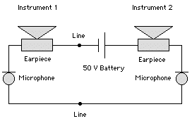
Each carbon microphone consists of a capsule containing carbon granules that are attached to a diaphragm. When the latter vibrates with the sound of a speaker’s voice, the electrical resistance of the granules changes, causing variations in the electrical current flowing around the circuit. These variations can then be heard in both of the moving-coil earpieces.
The speaker can also hear his or her own voice, an effect known as sidetone. This is essential, since it confirms that the phone is working. However, in the simple circuit shown above, each speaker is almost deafened by the sidetone.
A later development is the field telephone, as shown below:-

This uses an anti-sidetone induction coil (ASTIC) to reduce sidetone. When someone speaks into the phone, the voltage across the resistor opposes that produced by the ASTIC. However, when signals are received from the line the two voltages help each other. Modern phones work in the same way, but employ more sophisticated technology in place of an ASTIC.
The field telephone uses a battery in both instruments, ensuring communication in at least one direction. For convenience, modern telephone exchanges contain a central battery, with telephones wired as shown in this simplified diagram:-
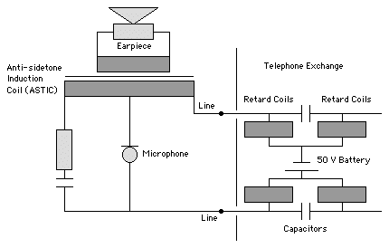
The retard coils prevent any speech signals from reaching the battery, whilst the pair of capacitors allow such signals to reach their destination via the exchange’s switching system. The exchange also sends a ringing signal to the phone as an alternating current (AC) signal, typically at 80 volts (V). In the UK, this is at a frequency of 17 Hz, often generated by a syncycle, which divides the domestic 50 Hz mains frequency by one-third.
Older telephone equipment uses pulse-dialling, involving repeated shorting-out of the phone line. The earliest devices have a rotary dial, although more modern instruments employ electronic circuitry. The diagram below shows the circuit of a standard rotary-dialling phone in simplified form:-
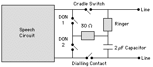
As you can see, the phone’s cradle switch disconnects much of the instrument when it’s not in use, whilst the dialler off-normal (DON) contacts prevent any unpleasant noises in the earpiece during dialling. The dialling contact is normally closed, but during dialling it opens for around 67 milliseconds (ms) with intervening opening periods of about 33 ms. As shown, the circuit used by the AC ringer is isolated from the direct current (DC) used for speech by means of a capacitor. The latter is usually fitted in the master socket (see below) and is shared by all the instruments on a line.
Fortunately, some of these complications are obviated by modern telephones and exchanges that support tone-dialling, where special tones are sent to the exchange for each number that’s dialled.
The following table shows the impedance of typical telephone components:-
| Component | Impedance (Ω) |
|---|---|
| Line Holding | 750 |
| Speech Retard | 80 + 80 |
| Internal Ringer | 500 |
| External Ringer | 500 + 500 |
| Hand-ringing | 500 |
The 6-way modular connector that’s used in the UK is shown below:-

The instrument cable fitted to such a plug is wired as shown below:-
| Pin | Wire | Circuit |
|---|---|---|
| 1 | Black | Business |
| 2 | White | Line (B) |
| 3 | Green | Earth |
| 4 | Blue | Ringing |
| 5 | Red | Line (A) |
| 6 | Orange | Business |
although most devices are only wired onto pins 2 to 5. The corresponding socket should be connected to permanent cables, which are usually wired as follows:-
| Pin | Wire | Circuit |
|---|---|---|
| 1 | Green | Business |
| 2 | Blue | Line (B) |
| 3 | Orange | Earth |
| 4 | White | Ringing |
| 5 | White | Line (A) |
| 6 | White | Business |
Once again, pins 1 and 6 are frequently left unconnected.
The original Post Office Series 700 telephone, as used in the UK, contains two rows of connection tags; an upper row containing tags 1 to 9 and a lower row containing 10 to 19. These should be wired to the incoming cable as shown below:-
| Wire | Circuit | Tags |
|---|---|---|
| White | Line (B) | 16, |
| Green | Earth | 12 |
| Blue | Ringing | 5 |
| Red | Line (A) | 8 |
The incoming circuit to your premises is usually provided at a master socket or a special connection box. Usually this is owned by and installed by the telephone company, and is fitted with spark suppressors to give limited protection from the effects of lightning. In the UK, it also incorporates a capacitor and a resistor for the anti-tinkle feature.
Only one master socket should be fitted to a line. All other sockets should be secondary sockets, also known as slave sockets, that lack the extra components found in a master socket. The wiring from the master socket to all of the slave sockets should be made up using two-pair (four-core) or three-pair (six-core) unscreened twisted-pair cable.
MacWorld magazine (UK), IDG Communications, 2002-2004
©Ray White 2004.
