 Channel Numbers and GM
A computer is an ideal device for storing a musical performance in the form of a sequence of events, usually in the form of a pattern of notes. Each of these notes has a particular timing, note length and pitch, and must be directed to play a specific instrument or voice.
A sequence can be played through an electronic musical instrument, such as an external synthesiser or software within the machine itself. In many instances, real sounds in the form of audio samples are used as an instrument. These can be pitched by ‘clocking out’ a sample at different rates, although better results are obtained by using separate samples for different pitches.
Various systems have been used to store musical data, although the most common format is MIDI, related to the Musical Instrument Digital Interface used on many electronic instruments. Although the interface itself is old-fashioned, its data structure is highly efficient and expandable.
The usual MIDI messages can be divided in the following groups:-
These include the most common type of message, such as Note On or Note Off. Each instruction of this kind refers to a MIDI channel, identified by a channel number which is assigned to a specific voice in a musical device. Any track that;s created in a sequence can be used to play the required voice by sending a message to the appropriate MIDI channel.
Each musical instrument can often be set up to respond in one of several modes:-
In this mode a single voice is triggered using one MIDI channel and no further sounds can play until this first note has ceased. This unusual and archaic mode is sometimes used to control an elderly analogue synthesiser, as connected to a MIDI system via a MIDI to analogue converter.
Poly is a modern mode in which polyphonic sounds of the same voice are triggered using one MIDI channel whilst non-voice messages are sent via a special channel known as the basic channel. The latter channel can default to channel 1 or can be selected using the instrument’s master controls.
Multiphonic mode, a variation of standard Poly mode. In this state multiple polyphonic sounds can be triggered using a specified MIDI channel for each voice.Omni on mode, which can sometimes be switched on or off in both Poly and Mono modes, allows a single voice to be triggered by all MIDI channels. For polyphonic operation, where more than one note is played at a time, several channels are needed, which means this mode is often best turned off.
Poly and Omni on modes. In other words they should play polyphonically from any channel. In reality, many devices only accept data from selected channels. In Omni off mode a device only accepts data on its basic channel.Program Change message can be used to switch any device on a specified channel into a preset state, but is usually used to select a predetermined sound or voice.Control Change messages are generated by the switches, foot pedals, or other controllers fitted on some MIDI devices, and can be used to adjust other devices whilst playing a sequence. Typically, such controls employ 14-bit resolution, stretching the capacity of MIDI to the limit. However, the transmitted data can be thinned, usually with little audible effect, or the receiving device can be programmed to do the job itself on receipt of a simple MIDI command.
These messages, also known as Sysex messages, often contain manufacturer’s proprietary codes for controlling or editing data in their products. Although details for System Exclusive codes are usually supplied, you’ll often encounter special software that obviates any need to understand them.
Several different types of message are used for synchronising other devices to a sequencer. Initially, the sequencer should send a Song Select message to indicate which song it’s about to play. A Start message should then be sent to the sequencer to initiate playback of the song.
Once it’s running, the sequencer sends regular Timing Clock messages at a rate of 96 clocks per whole note (semi-breve). By using these clocks to modify a Song Position Pointer register, each MIDI device knows how far the sequence has progressed. To return to a particular point in the sequence the sequencer must send a Song Position Pointer message to all devices.
In addition to the above messages, it’s also possible to convey timecode, the actual time of day of a recording in hours, minutes, seconds and frames. These messages allow other devices such as video and audio equipment to be synchronised to a sequencer. Two systems are used:-
This is the standard system for synchronisation. A Full MIDI Timecode message, also known as a Full Frame message, is sent when the source of timecode starts, stops or ‘drops out’. This is often followed by Quarter Frame messages, as sent during a continuous run of timecode.
Full MIDI Timecode message is actually a System Exclusive message. This point should be kept in mind when using any device that filters MIDI data.Both of these systems, devised by Mark of the Unicorn, are highly reliable alternatives to MTC that only employ System Exclusive messages. A full set of time information is sent at the start of a ‘run’ of timecode, which is then followed by up or down clock messages as timecode progresses.
Channel Numbers and GMMIDI requires every voice or sound in a device to be assigned a MIDI channel number. The table below shows examples of such assignments:-
| Channel | Voice |
|---|---|
| 1 | Piano |
| 2 | Bass |
| 3 | Brass or Sax |
| 4 | Guitar or Clavinet |
| 5 | Ensemble String |
| 6 | Human Voice |
| 7 | Woodwind |
| 8 | Organ |
| 10 | Drums |
However, a drum kit only uses one MIDI channel for all the sounds in the kit, which is useful when you’re short of MIDI channels. Each sound is assigned to a different note, which is only possible because percussion sounds aren’t normally played at a particular pitch. Here are some examples:-
| Note | Sound |
|---|---|
| 36 (C) | Bass Drum |
| 38 | Snare |
| 40 | Rim Shot |
| 41 | Lo Tom |
| 43 | Mid Tom |
| 45 | Hi Tom |
| 42 | Closed High-Hat |
| 44 | Half-closed High-Hat |
| 46 | Open High-Hat |
| 51 | Ride Cymbal |
| 54 | Crash Cymbal |
The MIDI Program Change message contains a program number that determines the voice to be used for a particular MIDI channel. As already mentioned, any instrument can be used with any channel, which can cause a sequence to be played with an ridiculous set of voices.
In 1991 the Japanese MIDI Standards Committee (JMSC) and the American Manufacturers’ Association agreed on Level 1 of the new General MIDI (GM) standard. This specified standardised program numbers for common sounds. A GM instrument, which must contain 128 standard GM sounds, complete with 24-note polyphony and 16-voice multitimbral operation, can then play sequences without the user having to worry about voice assignments.
General MID1 2 (GM 2) appeared in 1999. Instruments that confirm to this standard can play 32 sounds simultaneously, with support for two drum kits, whilst additional banks of instruments are accommodated via the GM Bank Select message. GM 2 also assigns specific tasks to formerly unassigned controllers and registered parameter numbers (RPNs) (see below).
GM Lite, introduced in 2001, accommodates those more modest instruments that can’t support the full panoply of GM 2 messages. Other extensions to the GM standard include:-
This system was developed by Roland to overcome the limit of 128 sounds imposed by GM. It uses the GM Bank Select message to select alternative sets of sounds known as variations.
These variations are organised rather cleverly. For example, a Program Change message of decimal 14 normally causes a GM device to select the Tubular Bells sound. However, if you precede this message by a GM Bank Select message (in the MSB, as described below) you’ll select Church Bell in a GS device. Fortunately, both these sounds are quite similar, which means that almost any kind of MIDI sequence should sound acceptable, even on a synthesiser that doesn’t support GS.
GS also uses non-registered parameter numbers (NRPNs) for controlling special functions, including reverberation and chorus effects. Although only GS-compatible synthesisers recognise these instructions, a sequence created on a GS device can still be played on a non-GS instrument.
Devised by Yamaha, this version of GM also provides its own kind of variations, as well as giving extra control over sounds and effects. Although sequences can be interchanged between GS and XG devices, each kind of device normally only recognises its own instructions, ignoring other types.
GM gives access to a drum kit on MIDI channel 10, with each note activating a different sound, as shown in the following example:-
| Note | Sound |
|---|---|
| 35 | Acoustic Bass Drum |
| 36 | Bass Drum 1 |
| 60 | High Bongo |
| 61 | Low Bongo |
| 80 | Mute Triangle |
| 81 | Open Triangle |
The following drum kits are normally provided:-
| 1 | Standard Kit |
|---|---|
| 9 | Room Kit |
| 17 | Power Kit |
| 25 | Electronic Kit |
| 26 | Analog Kit |
| 33 | Jazz Kit |
| 41 | Brush Kit |
| 49 | Orchestra Kit |
| 57 | SFX Kit |
This section provides an overview of MIDI messages, although General MIDI (GM) and its GS and XG variants aren’t included. For further details you should refer to the latest MIDI Specification, as published by the MIDI User Group. Also, to find how your devices respond to MIDI messages you should refer to the MIDI implementation chart provided with each product.
Hexadecimal (hex) values are shown in the following information, except where a single-digit value is given without a preceding zero: hence 0A is a hex value but 3 is a decimal number.
In hex notation each byte consists of two characters, each representing half a byte, otherwise known as a nibble. The most significant (MS) nibble is given by the left-hand character whilst the least significant (LS) nibble is to the right. Each digit can contain characters such as 0, 1, 2, 3, 4, 5, 6, 7, 8, 9, A, B, C, D, E, or F, accommodating numbers from 0 to 15.
A variable value can be expressed in hex using notation such as nn or vv, with any fixed nibbles shown directly, as in 8n or 0g (containing a fixed MS nibble of 8 and 0 respectively).
All MIDI messages begin with a status byte, with a value of between hex 80 and hex FF. Some status bytes are followed by one or more data bytes, with values of 00 to 7F, conveying extra information relating to the preceding status byte. For example, when a musical note is played, data bytes are used to convey its note number and the pressure applied to the key.
Status bytes are divided into Channel messages, transporting data over a particular MIDI channel, and System messages, which can be received by all devices on a MIDI circuit. The latter also include System Exclusive messages that are often only understood by special devices or equipment produced by a certain manufacturer. These categories are illustrated in the following diagram:-

The Channel messages all have status bytes in the range of 80 to EF. The various types of message, shown complete with mnemonics, are as follows:-
| Code | Channel | Hex |
|---|---|---|
| NOF | Note | 8n |
| NON | Note | 9n |
| PKP | Polyphonic | An |
| CCH | Control | Bn |
| PCH | Program | Cn |
| MCP | Monophonic | Dn |
| PWL | Pitch | En |
where n represents the MIDI channel number.
The System messages have status bytes in the range of F0 and FF, of which the System Common messages occupy F0 to F7, as shown below:-
| Code | System | Hex |
|---|---|---|
| SOX | Start | F0 |
| MTC | Midi | F1 |
| SPP | Song | F2 |
| SCH | Song | F3 |
| TRQ | Tuning | F6 |
| EOX | End | F7 |
whilst F8 to FF are used for System Real Time messages:-
| Code | System | Hex |
|---|---|---|
| CLK | Timing | F8 |
| STR | Sequence | FA |
| CNT | Sequence | FB |
| STP | Sequence | FC |
| SNS | Active | FE |
| RST | System | FF |

Each Channel message status byte contains a MIDI channel number in its least significant nibble. This allows the information to be directed to a device or voice in a synthesiser that has a corresponding channel number. The channel numbers in a receiving device can be assigned manually, although General MIDI (GM) equipment normally uses fixed numbers, as described above.
A simple instrument often only needs one channel, whereas a multitimbral synthesiser normally uses as many channels as it can accommodate. In the latter, the lowest numbered channel, known as the basic channel, is used for receiving information that’s not associated with a particular voice.
A Channel Voice message can be used to directly trigger a voice or instrument within a synthesiser. Only a device or voice with a matching channel will respond to such a message.
All voice messages, except Monophonic Channel Pressure, employ two data bytes. The first of these bytes specifies the note number whilst the second byte gives a velocity value, normally representing the pressure applied to the corresponding key on a keyboard.
The number of bytes to be transmitted are reduced to a minimum by using a mechanism known as running status. This ensures that the timing of musical material is maintained, even though MIDI sends data at a fairly slow rate. In the process, a string of data bytes is allowed to follow a single status byte without any other status bytes being transmitted. Using running status, the Note On status byte can be followed by any number of ‘note on’ or ‘note off’ data bytes. Each ‘note off’ data byte is similar to a ‘note on’ byte but contains a velocity value of zero, effectively switching off the note.
The channel voice messages are detailed below. A typical sequence of a status byte followed by two data bytes is represented in a form of Ss, Dd, Ee, where Ss is the status byte, whilst Dd and Ee are the data bytes. Each letter equals a nibble of data, corresponding to a digit in hex notation.
This indicates that a key has been released. The second data byte gives the speed of release or the off velocity but is often unused and set to hex 40. Messages are in the form:-
8n, kk, vv
________
n = MIDI Channel Number
kk = Note Number in hex
vv = Off Velocity, often
▪ 00 = off
▪ 01 = ppp
▪ 34 = mp
▪ 40 = Mid Position or
▪ 46 = mf
▪ 7F = fffThe following table and diagram should help you find the values of kk on a standard keyboard:-
| Note | kk | kk | Freq | |
|---|---|---|---|---|
| 1 | A0 | 21 | 15 | 27.500 |
| 4 | C1 | 24 | 18 | 32.703 |
| 40 | C4 | 60 | 3C | 261.265 |
| 49 | A4 | 69 | 45 | 440.000 |
| 88 | C8 | 108 | 6C | 4186.000 |
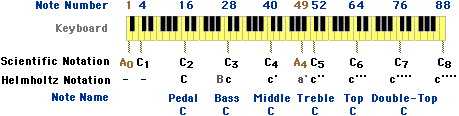
C0 instead of C1, C3 instead of C4 and C7 instead of C8.Terms such as ppp, mp, mf and fff should be familiar to those of a musical disposition. In the following arrangement a more linear coding method is used:-
| Dec | Hex | Meaning |
|---|---|---|
| 0 | 00 | Off |
| 14 | 0E | pppp |
| 20 | 14 | ppp |
| 25 | 19 | pp |
| 35 | 23 | p |
| 45 | 2D | mp |
| 55 | 37 | mf |
| 70 | 46 | f |
| 85 | 55 | ff |
| 100 | 64 | fff |
| 127 | 7F | ffff |
This indicates a key has been pressed. The second data byte is the applied pressure or on velocity.
9n, kk, vv, kk, vv, - - -
____________________
n = MIDI Channel Number
kk = Note Number
vv = On Velocity or
▪ 00 = Note Off using
Indicates the pressure applied to an individual key, although Monophonic Channel Pressure is often used in its place (see below).
An, kk, vv
_________
n, kk, vv: see above
Indicates pressure has been applied to the keyboard. This is often used in preference to Polyphonic Key Pressure but isn’t specific to a particular key being pressed.
Dn, vv
______
n, vv: see above
A Channel Mode message tells a device how to respond to subsequent voice messages. It can also be used to control parameters that are universal to a device, such as a synthesiser’s volume.
These messages are sent over a device’s basic channel. Usually, there’s only one basic channel, although more can be used, allowing one instrument to act as several independent synthesisers.
The Channel Mode messages are:-
This indicates that a control or switch has moved. The pairs of data bytes that follow the status byte can specify which continuous controller or switch has been adjusted and its setting.
The 32 14-bit controllers include GM Bank Select (0 and 32) Modulation Depth (1), Foot Controller (4), Portamento Time (5), Data Entry Slider (6) and Channel Volume (7), although some older instruments confuse 4 and 7. These controller values are normally encoded on a logarithmic scale, using a most significant byte (MSB) and optional least significant byte (LSB). They can be used in a non-standard way with an automated sound mixer, providing 64 faders with 7-bit control (0.8 dB resolution) or 32 faders with 14-bit control, plus switches.
The GM Bank Select message is used by both GS and XG equipment. Although the relevant MSB and LSB components are normally transmitted one after the other, GS devices normally convey useful information in the MSB whilst XG devices often expect the MSB to be 00 or 64. As a result, both GS and XG equipment can usually coexist in the same MIDI system without any problems.
Bank Select numbers or here to see the XG numbers. When you’ve finished looking, simply click on your browser’s Back button to return to this page.The 32 7-bit controllers include Sustain (Hold 1) Pedal, Portamento Pedal, Sostenuto Pedal and Soft Pedal switches, as well as Sound Variation Controllers, General Purpose Controllers and Effects Depth Controllers and other unassigned controllers.
The numerous switches include Data Increment Button, Data Decrement Button, two 14-bit Parameter Controllers, All Sound Off, Reset All Controllers and Local Control, as well as switches to set an instrument’s Channel Mode and to send an All Notes Off message. The Channel Mode switches are important, since they determine how a device handles Channel messages. In effect, four switches are used: Omni On or Omni Off and a ‘toggle’ action between Poly and Mono modes. This means that switching to Poly mode automatically switches any device out of Mono mode.
For a receiver with a basic channel of N the modes are:-
| Omni | P/M | Effect | |
|---|---|---|---|
| 1 | On | Poly | All |
| 2 | On | Mono | All |
| 3 | Off | Poly | Channel |
| 4 | Off | Mono | Channel |
For a transmitter with a basic channel of N the modes are:-
| Omni | P/M | Effect | |
|---|---|---|---|
| 1 | On | Poly | All |
| 2 | On | Mono | Mono |
| 3 | Off | Poly | All |
| 4 | Off | Mono | Single |
If a receiver can’t accept a mode it often ignores the message or may switch to Mode 1. In theory, instruments should also default to Mode 1 at startup, but most devices don’t actually do this.
The Control Change messages are shown below, where • indicates a message that’s specific to the GM 2 standard and † indicates a message that should be supported by GM Lite devices. The relevant decimal numbers are also shown in blue to assist in controller identification.
Bn, cc, vv, cc, vv, - - -
____________________
n = MIDI channel number
cc = controller number,
00 to 1F = MSB for 14-bit
0 00 = GM Bank Select•†
1 01 = Modulation Depth
2 02 = Breath Controller
3 03 = Unassigned
4 04 = Foot Controller
5 05 = Portamento Time
6 06 = Data Entry
7 07 = Channel Volume
8 08 = Channel Balance
9 09 = Unassigned
10 0A = Pan•
11 0B = Expression•†
12 0C = Effect Control 1
13 0D = Effect Control 2
14 0E = Unassigned
15 0F = Unassigned
16 10 = General Purpose
17 11 = General Purpose
18 12 = General Purpose
19 13 = General Purpose
20 to 31 14 to 1F =
20-3F = LSB for above controllers
0/32 20 = GM Bank Select
1/33 21 = Modulation Depth
2/34 22 = Breath Controller
3/35 23 = Unassigned
4/36 24 = Foot Controller
5/37 25 = Portamento Time
6/38 26 = Data Entry Slider†
7/39 27 = Channel Volume
8/40 28 = Channel Balance
9/41 29 = Unassigned
10/42 2A = Pan•
11/43 2B = Expression•
12/44 2C = Effect Control 1
13/45 2D = Effect Control 2
14/46 2E = Unassigned
15/47 2F = Unassigned
16/48 30 = General Purpose
17/49 31 = General Purpose
18/50 32 = General Purpose
19/51 33 = General Purpose
20/52 to 31/63 34 to 3F =
40 to 5F = 7-bit controllers
(vv = 00 to 3F for ‘off’,
0/64 40 = Sustain
1/65 41 = Portamento Pedal
2/66 42 = Sostenuto Pedal
3/67 43 = Soft Pedal
4/68 44 = Legato
5/69 45 = Hold 2 Pedal
6/70 46 = Sound Variation
7/71 47 = Sound Variation
8/72 48 = Sound Variation
9/73 49 = Sound Variation
10/74 4A = Sound Variation
11/75 4B = Sound Variation
12/76 4C = Sound Variation
13/77 4D = Sound Variation
14/78 4E = Sound Variation
15/79 4F = Sound Variation
16/80 50 = General Purpose
17/81 51 = General Purpose
18/82 52 = General Purpose
19/83 53 = General Purpose
20/84 54 = General
21/85 to 26/90 55 to 5A =
27/91 5B = Effects 1 Depth
28/92 5C = Effects 2 Depth
29/93 5D = Effects 3 Depth
30/94 5E = Effects 4 Depth
31/95 5F = Effects 5 Depth
60 to 7F = Switches
96 60 = Data Increment
97 61 = Data Decrement
98 62 = Non-Registered
99 63 = Non-Registered
100 64 = Registered
101 65 = Registered
102 to 119 66 to 77 =
120 78 = All Sound Off•†
121 79 = Reset All
122 7A = Local Control
123 7B = All Notes Off
124 7C = Omni Mode Off/All
125 7D = Omni Mode On/All
126 7E = Mono Mode On/All
vv = MM channels used
vv = 0 all available
127 7F = Poly Mode On/All
• Specific to the GM 2
† Should be supported by
* Not specific to any
◊ Often specific to
Indicates that a voice or patch has been selected.
Cn, pp
_____
n = MIDI Channel Number
pp = Program NumberIndicates the pitch bend controller has moved, using two data bytes for the 14-bit data. The sensitivity to the pitch bend control is determined within the receiver itself.
En, vv, VV
_________
n = MIDI Channel Number
vv, VV = Pitch Bend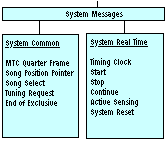
A System message is designed to be sent and received irrespective of the MIDI channel or channels used by a device. Each message is available to all devices in a MIDI system, although some devices don’t actually understand every kind of message.
A System Common message is available to all devices but doesn’t have any particular timing priority. The types of messages used are as follows:-
Indicates the current position within a current run of timecode. At the start of a run a Full MIDI Timecode message must be sent (see Real Time System Exclusive messages below).
One hundred messages are sent per second, although this only uses 7.5% of MIDI’s total bandwidth. Timecode is contained in a data byte spread over 8 messages. Hence a full update of timing data only occurs on every second frame of timecode.
F1, nd
_____
n = Timecode Message Type
00 = Frames LS Nibble
01 = Frames MS Nibble
02 = Seconds LS Nibble
03 = Seconds MS Nibble
04 = Minutes LS Nibble
05 = Minutes MS Nibble
06 = Hours LS Nibble
07 = Hours MS Nibble
d = Timecode nibbles
▪ Frame Count: xxxyyyyy:
xxx = Reserved
yyyyy = Frame Number
▪ Seconds Count: xxyyyyyy:
xx = Reserved
yyyyyy = Seconds Count
▪ Minutes Count: xxyyyyyy:
xx = Reserved
yyyyyy = Minutes Count
▪ Hours Count: xyyzzzzz:
x = reserved
yy = SMPTE Timecode Type:
0 = 24 frm/s
1 = 25 frm/s
2 = 30 frm/s Drop-frame
3 = 30 frm/s Non Drop
zzzzz = Hours CountThis is count of MIDI beats elapsed during a song, where one beat equals 6 MIDI clocks.
F2, pp, PP
_________
pp, PP = Pointer LSB, MSB
Selects the song to be played by a sequencer following a Sequence Start message (see below).
F3, ss
_____
ss = Song Number
These two codes should be avoided to ensure future compatibility.
This is rarely used and doesn’t employ any data bytes.
Indicates that System Exclusive data has ended (see below). No data bytes are used.
A System Real Time message is sent and received irrespective of MIDI channels but has the highest timing priority. These messages can be interposed between any bytes, separating other status bytes from their data, and can even be inserted in the middle of running status information.
These messages don’t have any accompanying data bytes.The following messages are used:-
A ‘pulsed’ message that drives a sequencer at a rate of six MIDI clocks per MIDI beat. Each device uses a song position pointer register to count these beats during a sequence.
There are 16 beats or 96 clocks per whole note. The relationship between note lengths, beats and clocks is given in the table below:-
| Note | Beats | Clocks |
|---|---|---|
| Semibreve | 16 | 96 |
| Minim | 8 | 48 |
| Crotchet | 4 | 24 |
| Quaver | 2 | 12 |
| Semiquaver | 1 | 6 |
Accommodates an optional feature that silences an instrument if its MIDI cables are accidentally disconnected. Any device that receives this signal will expect another every 300 milliseconds (ms). If this fails to appear the receiver then defaults to non-sensing mode and turns off all voices.
This lets you restore all instruments to normal. It shouldn’t be sent automatically at startup.
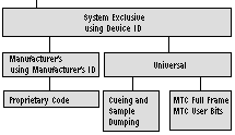
A System Exclusive message is a System message that’s only recognised by a particular kind of device. There are two types of message in this category:-
System messages this is sent to a specific piece of equipment, which means that each device in a MIDI system must have a unique device ID. In practice, this usually corresponds to the basic channel number, as used for Channel Mode messages.All of these messages begin with hex F0, used for the Start of Exclusive (SOX) status byte.
The manufacturer’s System Exclusive message is in the following form:-
F0, ii, xx, - - - xx, F7
__________________
ii = manufacturer’s ID:
01 = Sequential Circuits
02 = Big Briar
03 = Octave Plateau
04 = Moog
05 = Passport
06 = Lexicon
07 = Kurzweil
08 = Fender
09 = Gulbransen II
0A = Delta Lab
0B = Sound Composition
0C = General Electro Music
0D = Techmar
0E = Matthews R & D
0F = Ensoniq
10 = Oberheim
11 = PAiA
12 = Simmons
13 = Gentle Electric
14 = Fairlight
15 = J L Cooper
16 = Lowery
17 = Linn
18 = Emu
20 = Bon Tempi
21 = SIEL
22 = IRCAM
23 = Synthaxe
24 = Hohner
25 = Crumar
26 = Solton
27 = Jellinghaus
28 = CTS
29 = PPG
2B = SSL
2F = Elka
40 = Kawai
41 = Roland
42 = Korg
43 = Yamaha
44 = Casio
45 = Akai
xx = System exclusive
The following messages are directed to a specific device by using the device’s ID:-
This message sends instructions to a device that uses MIDI timecode, such as a multi-track tape recorder or a sequencer.
F0, 7E, nn, 04, jj, hh, mm,
______________________
7E = ID for Non Real
nn = Device ID
04 = Sub ID 1 for MTC
jj = Sub ID 2:
▪ 00 = Special
▪ 01 = Punch In Point
▪ 02 = Punch Out Point
▪ 03 = Delete Punch In
▪ 04 = Delete Punch Out
▪ 05 = Event Start Point
▪ 06 = Event Stop Point
▪ 07 = Event Start Point
▪ 08 = Event Stop Point
▪ 09 = Delete Event Start
▪ 0A = Delete Event Stop
▪ 0B = Cue Point
▪ 0C = Cue Point with
▪ 0D = Delete Cue Point
▪ 0E = Event Name In
hh = Hours and SMPTE type:
Containing bits organised
yy = SMPTE Timecode Type:
▪ 00 = 24 frm/s
▪ 01 = 25 frm/s
▪ 02 = 30 frm/s Drop-frame
▪ 03 = 30 frm/s Non Drop
▪ zzzzz = Hours (0 to 23)
mm = Minutes
ss = Seconds
ff = Frames
gg = Fractional Frames
xx = 14-bit Event Number
yy = 14-bit Event Number
▪ 00 = Timecode Offset
▪ 01 = Enable Event List
▪ 02 = Disable Event List
▪ 03 = Clear
▪ 04 = System Stop
▪ 05 = Event List Request•
aa = Additional Info:
MIDI data is sent as
If jj = 0E (Event Name in
F7 = End Of System
• Sent by an MTC master
All of the following Universal System Exclusive messages are concerned with the transfer of audio samples via MIDI.
For best results MIDI circuits should be connected in both directions, so as to create a closed loop complete with handshaking. After two seconds of waiting for any handshake signals the system should normally default to open loop operation.
This message is sent prior to the transfer of sample data between a controlling device and a sampler.
F0, 7E, nn, 03, ss, SS, F7
______________________
7E = ID for Non Real Time
nn = Device ID
03 = Sub ID 1 for Sample
ss, SS = Stored Sample
This message is transmitted before sending an actual sound sample. Where two or three data bytes are used the LSB is sent first.
F0, 7E, nn, 01, ss, SS, bb,
______________________
7E = ID for Non Real Time
nn = Device ID
01 = Sub ID 1 for Dump
ss, SS = Stored Sample
bb = Number of Bits
pp, pp, PP = Sample Period
mm, mm, MM = Sample
xx, xx, XX = Sustain Loop
yy, yy, YY = Sustain Loop
tt = Loop Type:
▪ 00 = Forward
▪ 01 = Forward/backward
F7 = End of SystemThis indicates if a device can accept the data as defined in the Sample Dump Header message.
F0, 7E, nn, mm, pp, F7
___________________
7E = ID for Non Real Time
nn = Device ID
mm = Handshake Mode:
▪ 7C = Wait — further
▪ 7D = Cancel — device
▪ 7E = Not Acknowledged
▪ 7F = Acknowledged (ACK)
pp = Packet Number
F7 = End of SystemThis message is used for the actual process of dumping a sample. The time taken for a transfer can be up to ten times the sample’s real duration or even longer.
F0, 7E, nn, 02, pp, dd, dd,
_____________________
7E = ID for Non Real Time
nn = Device ID
02 = Sub ID 1 for Sample
pp = Packet Number
dd = Data Packets
cc = Checksum — of all
Each data packet of 120 bytes is organised as follows:-
| Sample | Bytes/ | Words/ |
|---|---|---|
| 8 to 14 | 2 | 60 |
| 15 to 21 | 3 | 40 |
| 22 to 28 | 4 | 30 |
The following messages contain time-related information for a device with a matching device ID:-
This message should always be sent at the beginning of a run of timecode.
F0, 7F, nn, 01, 01, hh, mm,
______________________
7F = ID for Real Time
nn = Device ID (7F to
01 = Sub ID 1 for MIDI
01 = Sub ID 2 for Full
hh, mm, ss, ff = Timecode
These bits are usually fixed throughout a run of timecode, although they don’t have to be. The information should correspond to that contained in the user bits of SMPTE timecode.
F0, 7F, nn, 01, 02, 0W, 0w,
_______________________
7F = ID for Real Time
nn = Device ID (7F to
01 = Sub ID 1 for MIDI
02 = Sub ID 2 for User Bits
W, w = User Byte 1
X, x = User Byte 2
Y, y = User Byte 3
Z, z = User Byte 4
g = SMPTE Binary Group
These messages are used in GM 2 equipment. They include Master Fine Tuning, Master Coarse Tuning, Reverb Type, Reverb Time, Chorus Type, Chorus Modulation Rate, Chorus Modulation Depth, Chorus Feedback, Chorus Send to Reverb, Controller Destination Setting, Scale/Octave Tuning Adjust and GM System On.
This is a special message that conveys text, as required when sending MIDI information over the Internet via an application such as Midi Phone.
F0, 00, cc, F7
____________
00 = ID for Text
cc = ASCII code for singleThis method of coding can only be used with real ASCII characters whose codes are in the range of 00 to 7F, not special symbols represented by higher codes from 80 to FF.
©Ray White 2004.
